For leading mobile network operators (MNOs), 5G is mainly about offering high-speed connectivity to consumers, on devices that support fifth-gen (5G-NSA and 5G-SA) network services. To smoothly transition from the existing legacy core to 5G, MNOs have two pathways: Non-Standalone (NSA) or Standalone (SA) architecture. And while they are both means to the same end, NSA and SA are structurally and functionally different.
5G Networks can be 5G-NSA or 5G-SA architecture
NSA allows operators to leverage their existing network investments in communications and mobile core instead of deploying a new core for 5G. 5G Radio Access Network (RAN) can be deployed and supported by the existing Evolved Packet Core (EPC), lowering CAPEX and OPEX. To further lower network operating costs, operators can adopt the virtualization of Control and User Plane Separation (CUPS) along with software-defined networking (SDN). These initial steps will help quickly unlock new 5G revenue streams and offer faster data speeds.
5G-SA is a completely new core architecture defined by 3GPP that introduces major changes such as a Service-Based Architecture (SBA) and functional separation of various network functions. Its architecture has the definite advantage of end-to-end high-speed and service assurance, particularly useful for MNOs who are set to commence new enterprise 5G services such as smart cities, smart factories, or other vertically integrated market solutions. The deployment model enables the rapid introduction of new services with quick time-to-market. However, it means additional investment and complexities of running multiple cores in the network.
Architecturally, NSA includes a new RAN, deployed alongside the 4G or LTE radio with the existing 4G Core or EPC. 5G SA, on the other hand, includes a new radio along with the 5G Core (5GC), comprising completely virtualized cloud-native architecture (CNA) that introduces new ways to develop, deploy, and manage services. 5GC supports high-throughput for accelerated performance than the 5G network demands. Its virtualized service-based architecture (SBA) makes it possible to deploy all 5G software network functions using edge computing.
5G Standalone (SA) vs 5G Non-Standalone (NSA)
5G-SA Architecture
According to asurvey, 37% of MNOs will deploy 5G SA within two years; 27% of operators plan to deploy 5G SA within 12 to 18 months with an additional 10% increase within 24 months. 5G SA architecture will allow operators to address the fifth generation of mobile communications, including enhanced mobile broadband, massive machine-to-machine communications, massive IoT, and ultra-low latency communications.
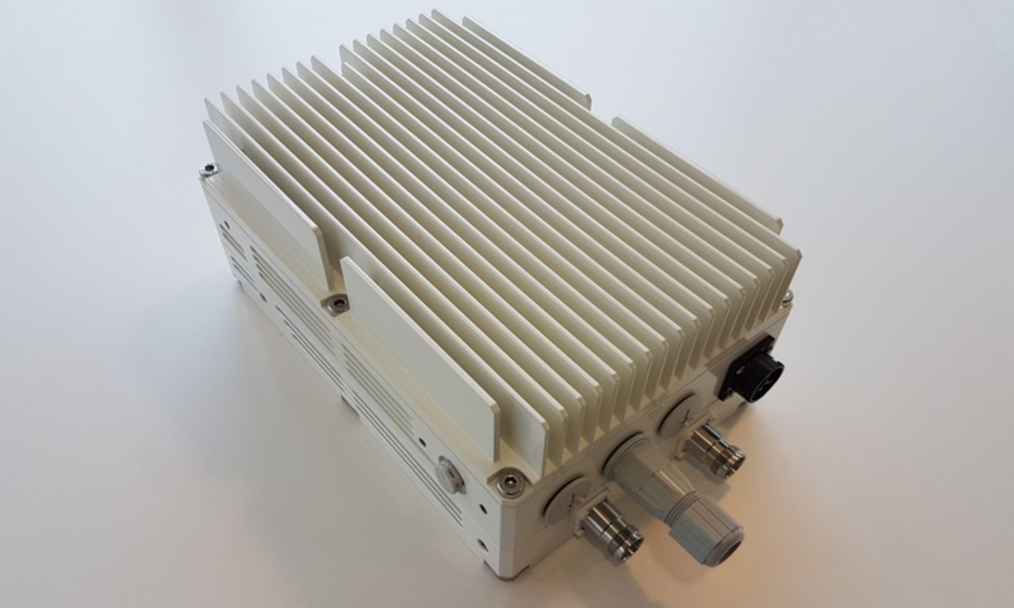
CableFree Remote Radio Head (RRH) used for 5G-SA and 5G-NSA networks
Standalone 5G-NR comprises a new end-to-end architecture that uses mm-Waves and sub-GHz frequencies and this mode will not make use of the existing 4G LTE infrastructure. The SA 5G NR will use enhanced mobile broadband (eMBB), Ultra-Reliable and Low Latency Communications (URLLC), and huge machine-type communications (mMTC) to implement multi-gigabit data rates with improved efficiency and lower costs.
5G SA also enables more advanced network slicing capabilities, helping operators rapidly transition to both 5G New Radio (NR) and 5G as the core network. Network slicing, URLLC, and mMTC bring ultra-low latency along with a wide range of next-gen use cases like remote control of critical infrastructure, self-driving vehicles, advanced healthcare, and more. However, the NR advanced cases are not backward compatible with the EPC, which is the framework that provides converged voice and data on a 4G LTE network. The level of reliability and latency that 5G provides will be indispensable for handling smart-grid control machines, industrial automation, robotics, and drone control and coordination.
5G-NSA Architecture
NSA-5G NR is considered as the early version of SA 5G NR mode, in which 5G networks are supported by existing LTE infrastructure. It fundamentally concentrates on eMBB, where 5G-supported handsets and devices will make use of mmWave frequencies for increased data capacity but will continue to use existing 4G infrastructure for voice communications.
NSA helps MNOs launch 5G quickly for eMBB to get a competitive edge in the telecom market. NSA also helps leverage its existing LTE/VoLTE footprint to maximize the LTE installed base and boost capacity while increasing delivery efficiency. It will not support network slicing, URLLC, and mMTC, but its higher broadband speeds will enable services such as video streaming, augmented reality (AR), virtual reality (VR), and an immersive media experience.
Non-Standalone 5G NR will provide increased data-bandwidth by using the following two new radio frequency ranges:
Frequency range 1 (450 MHz to 6000 MHz) – overlaps with 4G LTE frequencies and is termed as sub-6 GHz. The bands are numbered from 1 to 255.
Frequency range 2 (24 GHz to 52 GHz) – is the main mmWave frequency band. The bands are numbered from 257 to 511.
Technical Differences between 5G SA and 5G NSA
The main difference between NSA and SA is that NSA provides control signaling of 5G to the 4G base station, whereas in SA the 5G base station is directly connected to the 5G core network and the control signaling does not depend on the 4G network. In simple terms, NSA is like adding a solid-state drive to an old computer, which can improve the system’s performance, while SA is like replacing it with a new computer that has newer technologies and optimum performance.
Some benefits include:
5G-NSA is a low-cost update of core compared to a 5G Core needed for 5G-SA.
5G-NSA eases 5G network deployments as it reuses existing 4G facilities, thus allowing rapid time to market for 5G mobile broadband.
With NSA, the deployment is faster and time-to-market is lower, as 4G locations can be used to install 5G radio. SA requires building 5G base stations and the back-end 5G core network to fully realize the characteristics and functions of 5G.
SA involves a 5G core with SBA for scalability and flexibility to deliver a superfast network with ultra-low latency for advanced 5G use cases.
5G Usage Scenarios in NSA and SA Operation
The requirements of 5G NR for the SA provide a complete set of specifications for the 5G core network that goes beyond NSA. The three major usage scenarios defined for 5G by the 3GPP and GSMA include:
Enhanced mobile broadband (eMBB)
Ultra-reliable and low latency communications (URLLC)
Massive machine-type communications (mMTC)
Future 5G Networks Include both NSA and SA
Early adopters of 5G primarily focus on 5G-NSA deployments as they compete to deliver 5G speeds with a quick time to market. These MNOs can move to SA-based architecture over a period of time, which most plan to do. 5G-NSA deployment remains a mainstream solution given its ability to handle both 4G- and 5G-based traffic, keeping these early adopters ahead of their competition as they undertake their network transformation. 5G devices are not widespread so the need for 5G-SA-based architecture is still nascent.
For the future, the convergence of NSA and SA will help operators move to a full 5G network. A complete virtualized 5G architecture will allow MNOs to migrate and choose varied functionalities of their existing NSA solution to the 5GC platform, as new 5G services are launched, allowing them to monetize their investment gradually rather than move all at once and enabling them to recover their costs over time.
Although 5G-SA is a more mature network architecture compared to 5G-NSA, NSA will continue to be the more commonly chosen path to 5G. All NSA single-mode 5G phones launched this year or early next year will be valid for a decade, and as SA architecture permeates, more and more 5G-SA devices will be in our homes and businesses.
Explaining 5G NR PRACH function, contents and mapping
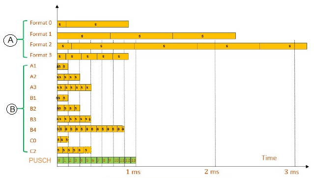
PRACH is used to carry random access preamble from UE towards gNB (i.e. 5G NR base station). • It helps gNB to adjust uplink timings of the UE in addition to other parameters. • Zadoff chu sequences are used to generate 5G NR random access preamble similar to LTE technology. • Unlike LTE, 5G NR random access preamble supports two different sequence lengths with various format configurations as shown in the figure. The different formats help in wide deployment scenarios.
Random Access Preamble
A: Long sequence of length 839 B: Short sequence of length 139 s: Zadoff chu sequence
Long Sequence
The 839 long sequence uses four preamble formats like LTE. These formats are designed for large cell deployment in FR1 (Sub-6 GHz range). They use subcarrier spacing of 1.25 KHz or 5 KHz.
Short Sequence
The 139 short sequence uses nine preamble formats. These formats are designed for small cell deployment including indoor coverage. These preamble formats are used for both FR1 (sub-6 GHz) and FR2 (mmwave) ranges. In FR1, it supports 15 or 30 KHz where as in FR2, it supports 60 or 120 KHz. subcarrier spacing.
5G NR PRACH physical layer processing
• PRACH uses same FFT as used for data. • OFDM baseband signal generation for PRACH is defined in 3GPP TS 38.211 section 5.3.2. • Engineers often come across situations (test cases) in which UE does not receive response from gNB for the PRACH message transmitted by it. During such scenarios, they need to analyze the test case with respect to various layers such as radio link, physical layer (L1) and last upper layer messages. This helps them diagnose the radio network issues and find root cause of any problems reported.
5G NR Terminologies – 5G Subcarrier Spacing, 5G Frame & Subframe, Slot and Symbol
Explaining 5G Subcarrier spacing as compare to LTE, 5G Frame and Subframe, possibilities of different type of 5G NR slot depending upon the different subcarrier spacing and OFDM symbol:
5G Subcarrier Spacing
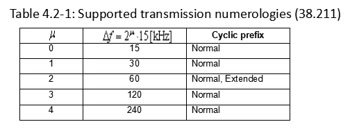
In 5G NR, subcarrier spacing of 15, 30, 60, 120 and 240 KHz are supported.
As you see here, each numerology is labled as a parameter (u, mu in Greek). The numerology (u = 0) represents subcarrier spacing of 15 kHz which is same as LTE. And as you see in the second column the subcarrier spacing other than 15KHz, for 5G NR.
NOTE: In LTE, there is only type of subcarrier spacing (15 KHz), whereas in NR, multiple types of subcarrier spacing are available.
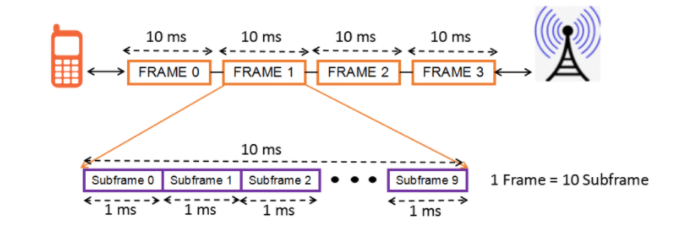
5G Frame and Subframe
Downlink and uplink transmissions are organized into frames with 10ms duration, each consisting of ten subframes of 1ms
Each frame is divided into two equally-sized half-frames of five subframes each with half-frame 0 consisting of subframes 0 – 4 and half-frame 1 consisting of subframes 5 – 9.
In Total, there are 10 subframes in one frame.
5G Slot
Slot length gets different depending on different subcarrier spacing. The general tendency is that slot length gets shorter as subcarrier spacing gets wider. Actually this tendency comes from the nature of OFDM.
Number of slots per subframe varies with carrier spacing
There can be 1, 2, 4, 8, or 16 slots per subframe
NOTE: In LTE, there are fixed two slots per subframe, but in NR, no. of slot may vary.
5G OFDM symbol
The number of symbols within a slot does not change with the numerology or subcarrier spacing.
OFDM symbols in a slot can be classified as ‘downlink’ (denoted ‘D’), ‘flexible’ (denoted ‘X’), or ‘uplink’ (denoted ‘U’).
In a slot in a downlink frame, the UE shall assume that downlink transmissions only occur in ‘downlink’ or ‘flexible’ symbols.
In a slot in an uplink frame, the UE shall only transmit in ‘uplink’ or ‘flexible’ symbols.
The number of symbols per slot is 14 (in case of Normal CP)
The number of symbols per slot is 12 (in case of Extended CP)
NOTE: In NR slot format, DL and UL assignment changes at a symbol level (in LTE TDD the UL/DL assignment is done in a subframe level)
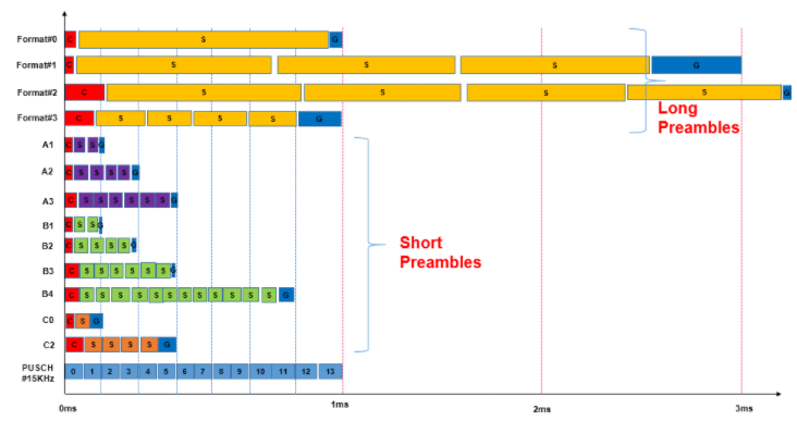
Understanding 5G-NR RACH Preamble Types: Long and Short Preambles
A preamble is send by UE to gNB over PRACH channel to obtain the UL synchronization. Similar to LTE, in 5G NR there are 64 preambles defined in each time-frequency PRACH occasion. The preamble consists of two parts cyclic prefix (CP) and Preamble Sequence.
In 5G NR, there are 13 types of preamble format supported known as Format 0, Format 1, Format 2,Format 3,Format A1,Format A2,Format A3,Format B1, Format B2, Format B3, Format B4, Format C0, Format C1. These 13 types of preamble format can be grouped into two categories:
Long Preamble
Short Preamble
Differences in the time domain of different preamble formats includes different CP length, Sequence Length, GP length and number of repetitions can be seen in below picture.
Long Preamble Characteristics
Long preambles are based on a sequence length L=839
Sub-carrier spacing for long preambles can be either 1.25 Khz or 5 Khz
Numerology used for long preambles is different from any other NR transmissions
Origin of long preambles partly from the preambles used for LTE
Long preambles can only be used for FR1 frequency bands which is below 6 Ghz
There are four different formats for the long preamble name Format#0, Format#1, Format#2 and Format#3
The preamble format is part of the cell random-access configuration and each cell is limited to a single preamble format
NR preamble format 0 and 1 are identical to the LTE preamble formats 0 and 2
A long preamble with 1.25 kHz numerology occupies six resource blocks in the frequency domain, while a preamble with 5 kHz numerology occupies 24 resource blocks
Short Preamble Characteristics
Short preambles are based on a sequence length L=139
The sub-carrier spacing for short preambles is aligned with the normal NR sub-carrier spacing i.e. 15Khz, 30Khz, 60Khz and 120Khz.
Short preambles use a sub-carrier spacing of:
15 Khz or 30 Khz in the case of operation below 6 Ghz (FR1)
60 Khz or 120 Khz in the case of operation in the higher NR frequency bands (FR2).
A short preamble occupies 12 resource blocks in the frequency domain regardless of the preamble numerology
The short preambles are, in general shorter than the long preambles and often span only a few OFDM symbols
Short preambles formats are designed such that the last part of each OFDM symbol acts as a CP for the next OFDM symbol and the length of a preamble OFDM symbol equals the length of data OFDM symbols
In most cases it is therefore possible to have multiple preamble transmissions multiplexed in time within a single RACH slot (occasion). In other words, for short preambles there can may be multiple RACH occasions in the frequency domain as well as in the time domain within a single RACH slot .
5G NR supports mix of the “A” and “B” formats to enable additional formats like A1/B1, A2/B2, and A3/B3.
Short preamble formats A and B are identical except for a somewhat shorter cyclic prefix for the B formats.
Preamble formats B2 and B3 are always used in combination with the corresponding A formats (A2 and A3)
Short preambles are design to targeting the small/normal cell and indoor deployment scenarios
Short preambles allows the gNB receiver to use the same fast Fourier transform (FFT) for data and random-access preamble detection.
These preambles are composition of multiple shorter OFDM symbols per PRACH preamble,makes them more robust against time varying channels and frequency errors.
Short preambles supports analog beam sweeping during PRACH reception such that the same preamble can be received with different beams at the gNB
Spectral efficiency is an important consideration for 5G-NR radios, as it was for 4G/LTE: The amount of information that fits in a given channel bandwidth or one just say how efficiently can that piece of spectrum be used to transmit information.
There is a hard limit to how much data can be transmitted in a given bandwidth – this limit is well-known as the Shannon-Hartley Theorem and commonly referred to as the Shannon limit.
Spectral efficiency is usually expressed as “bits per second per hertz,” or bits/s/Hz, defined as the net data rate in bits per second (bps) divided by the bandwidth in hertz. Net data rate and symbol rate are related to the raw data rate which includes the usable payload and all overhead.
raw data rate = Payload + Overhead
net data rate = raw data rate – overhead
Spectral efficiency = net data rate in bps / Channel Bandwidth in Hz
For example, a system uses channel bandwidth as 2 MHz and it can support a raw data rate of say 15 Mbps, assuming 2 Mbps as overhead then net date rate will be as 13 Mpbs, then its spectrum efficient can be calculated as follows:
Spectral efficiency= 13 x 10^6 / 2 x 10^6 = 6.5 bits/second/Hz
Calculating Spectral Efficiency for LTE:
An LTE system can support a maximum channel bandwidth as 20 MHz (Not including Carrier Aggregation). Its symbol rate can be calculated as
Symbols/Second = 1200 x 14 x 1000 = 16,800,000 Symbols/Second
Considering 64-QAM as highest modulation for downlink each symbol can carries 6 bits provide raw data rate as follows:
raw data rate = 16,800,000 x 6 = 100.8 Mbps (No MIMO considered)
Consider 4×4 MIMO: theoretically it makes raw data rates four times i.e. 400 Mbps. assuming 25 % as overhead the net data rate will be as 300 Mbps. Similarly data rate can be calculated for uplink . In a 1×1 LTE uplink there is no MIMO, so Max raw data can be 100 Mbps with 64-QAM support in Uplink and after deducted 25% overhead net data rate for uplink will be 75 Mbps. Uplink net date with 16-QAM will be 51 Mbps.
Downlink Spectral Efficiency = 300 x 10^6 bps / 20 x 10^6 Hz = 15 bits/second/Hz
5G New Radio is capable of providing a downlink throughput 2.31 Gbps and uplink throughput of 2.47 Gbps with certain configuration shown below assuming 100 MHz channel bandwidth. (Single carrier component)
Downlink Spectral Efficiency = 2.31 x 10^9 bps / 100 x 10^6 Hz = 23 bits/second/Hz
Uplink Spectral Efficiency = 2.47 x 10^9 bps / 100 x 10^6 Hz = 24 bits /second / Hz
Note: The values shown here are just theoretical value considering sensible baseline assumptions. Real-world network performance may differ.
For Further Information
For more information on Spectral Efficiency of 5G-NR radios,
Estimating the Maximum Throughput and 5G Capacity for modern Wireless Networks is complex and requires understanding of the 5G standards. This page is aimed at summarising what’s involved:
5G Maximum Capacity Estimation
Throughput estimation for 5G is complex, involving many factors and deep knowledge of the 5G standards. However, the rough estimation for a maximum throughput can roughly be estimated by following equation:
From:
< 38.306 – 4.1.2 Max data rate without ue-CategoryDL and ue-CategoryUL >
5G Capacity:
The meaning of each parameter in this equation is as follows:
5G Capacity Formula
Explaining the formula in more detail:
For 5G NR, the approximate data rate for given number of aggregated carriers in a band or band combination is calculated using the above equation or formula. The following fields are used in 5G NR throughput calculation:
➤J : number of aggregated component carriers in a band or band combination ➤Rmax : 948/1024 • For the j-th CC, Vlayers(j) is the maximum number of layers ➤Qm(j) : Maximum modulation order, Qm is 2 for QPSK, 4 for 16QAM, 6 for 32QAM, 8 for 256QAM ➤f(j) : Scaling factor, can take any value from 1/0.8/0.75/0.4 ➤μ : 5G NR Numerology, can take any value from 0 to 5. ➤Tsμ : Average OFDM symbol duration in a subframe for μ value, • Tsμ = 10-3/(14*2μ). ➤NPRBBW(j),μ : Maximum RB Allocation in bandwidth, BW(j)with numerology (μ), BW(j) is UE supported maximum Bandwidth in given band or in band combinations. REs are grouped into PRBs (Physical Resource Blocks). Each PRB consists of 12 Subcarriers. ➤OH(j) : Overhead which takes any of the following values. • [0.14] → Frequency Range FR1 for DL • [0.18] → Frequency Range FR2 for DL • [0.08] → Frequency Range FR1 for UL • [0.10] → Frequency Range FR2 for DL
Above mentioned formula has been used along with 5G NR Physical layer parameters and other 5G NR system parameters in order to develop 5G NR throughput calculator. One can refer following pdf which covers snapshot of 3GPP TS 38.306 document for more information on 5G NR data rate calculation. The maximum transmission bandwidth configuration NRB for each UE channel bandwidth and subcarrier spacing are specified in the tables below.
3GPP References
• 3GPP TS 38.306 V15.2.0 (2018-06)
Maximum 5G Throughput & Capacity Calculators
We noted a few of examples of the maximum throughput calculators on the Internet as listed below. Disclaimer: these are what we found on the Internet – results may vary and accuracy is not known or warranted.
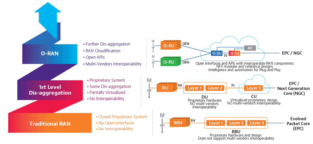
An Open Radio Access Network (O-RAN) is a disaggregated approach to deploying mobile fronthaul and midhaul networks built entirely on cloud native principles. O-RAN underscores streamlined 5G RAN performance objectives through the common attributes of efficiency, intelligence and versatility. Open RAN deployed at the network edge will benefit 5G applications such as autonomous vehicles and the IoT, support network slicing use cases effectively, and enable secure and efficient over-the-air firmware upgrades.
O-RAN is an evolution of the Next Generation RAN (NG-RAN) architecture, first introduced by the GSMA’s 3GPP in their release 15 (5G version 1) technical specification TS 38.401. The O-RAN Alliance formed to undertake the advancement of NG-RAN philosophies, expanding on the scope of what was originally outlined by the 3GPP. Comprising over 1601 member companies, the O-RAN alliance issues specifications and releases open source software under the auspices of the Linux Foundation.
TS 38.401 decomposed the existing Baseband Unit (BBU) into two functional components, a Distributed Unit (DU) and Central Unit (CU). Conforming to modern control user plane separation (CUPS) constructs, the Central Unit can be further decoupled into distinct control plane (CU-CP) and user plane (CU-UP) functions. Replacing the monolithic BBU with the CU/DU allows for new deployment models which feature centralized packet processing functions, while laying the groundwork for separating baseband functions from the (remote) radio unit (RRU/RU).
ORAN explained: Picture courtesy VIAVI solutions
O-Ran Benefits
Operational efficiencies have been realized through past RAN innovations such as cloud RAN (cRAN), but previous advancements did not free operators from vendor lock-in. By enabling an open, multi-vendor RAN ecosystem, O-RAN introduces cloud-scale economies and competition to the RAN. Marketplace factors, combined with a more elastic and flexible RAN architecture that is already taking shape through virtualization, can enable much faster time to market (TTM) than was previously possible.
Moving away from the vendor-specific RAN paradigm not only enables more flexibility for operators, it also minimizes the “secret sauce” that leaves them reliant on a single vendor for all aspects of RAN implementation and optimization.
Competition and proliferation resulting from of new entrants can potentially drive down O-RAN equipment costs. The inter-carrier, interoperability aspects of Open RAN can also be used to increase efficiencies for existing LTE networks as they continue to incorporate the virtualization and disaggregation that are prerequisite 5G RAN deployment.
A CableFree Remote Radio Head (RRH) used for O-RAN networks
This affords numerous technical and operational advantages, regardless of whether the RRU, DU and CU remain co-located within a 5GNodeB (gNB), like existing NodeB RRU/BBU implementations, or the CU is physically deployed to a more centralized location. The centralization of the CU in an aggregation site reduces costs and accelerates the implementation of dynamic and highly automated multiaccess edge compute (MEC) clouds for the RAN (aka C-RAN). This functional decoupling will also enable the adoption of modern transport protocols which can also align with the 5G core user plane (i.e. SRv6) while easing the addition of new latency, high-bandwidth, AI/ML-driven applications.
The deployment of NG-RAN components is defined as being with or between the fronthaul, midhaul and backbone network. Open interfaces are described as either lower-layer splits (LLS), in the case of the RU to DU connection, or higher-layer splits (HLS) as with the link between the DU and CU. This nomenclature is descriptive of the OSI layer (i.e. L1/L2/L3) exposed by the interface and handled by the NG-RAN function. Where components are instantiated will depend on the requirements of the service slice. A low latency service might demand a CU be co-located with the DU in the access layer while a slice supporting a simple machine to machine communications application would scale more cost effectively with a CU within the network core.
NG-RAN clearly defines the DU and CU plus the F1, E1, Xn and NG between them and the core network but stops short of outlining the service management framework and interfaces required for the RAN to operate within an orchestrated and automated cloud environment. TS 38.401 also fails to address the RU-DU interface. Without further definition, it would be logical to adopt the exiting Common Public Radio Interface (CPRI) defined between the RRU-BBU. Although theoretically a standard, this interface has been heavily modified by individual vendors, effectively locking their RRU to their BBU.
While CPRI is a high-speed serial interface, the bandwidth demands of 5G will stretch the limits of local fiber and increase the need for more radio units. Current implementations do not allow for the DU to reduce this burden by offloading some of its functionality to the RU. While the enhanced CPRI (eCPRI) interface was originally proposed as an alternative, this specification was also developed by just four2 large vendors. The O-RAN Alliance has therefore taking on the task of defining new Open Fronthaul user and management plane interfaces between the DU and RU.
To ensure openness, O-RAN decouples hardware and software into 3 layers: The commercial off the shelf (COTS) merchant silicon (including x86), a hardware abstraction layer and an application layer, where the RAN functions reside. Ensuring each layer is vendor agnostic, the O-RAN alliance has specified a list of requirements for a cloud platform which supports the execution of O-RAN network functions. This is referred to as the O-RAN Cloud Platform, or O-Cloud. Deploying O-RAN functions on x86 hardware in cloud native environments using lightweight (OS virtualization) containers demands a strong emphasis on data plane acceleration. This must be achieved at the application level, as these functions will not have access to the Kernel. As such, solutions may be specific to each O-RAN CNF but leverage standard techniques such as DPDK and FD.io or employ more advanced techniques.
O-RAN challenges
Creating seamless interoperability in a multi-vendor, open ecosystem introduces new test, management and integration challenges that require diligence and cooperation to overcome. In the single-vendor model, accountability is a foregone conclusion and problem isolation and troubleshooting are managed through an established command structure.
Dispersion of vendors could potentially lead to finger pointing when root cause identification is inconclusive. These same complications could plague on-time launch schedules and revenue growth by diluting management and orchestration responsibilities across an array of new O-RAN players.
The enticing Open RAN concept of flexible interoperability also brings challenges for test and integration. To fulfill the O-RAN promise of reduced OPEX and total cost of ownership (TCO), operators must take responsibility for multi-vendor, disaggregated elements and make sure they perform together to maintain QoE standards.
With Open RAN reducing the barrier to entry for dozens of new players, interoperability is a paramount concern for both the O-RAN ALLIANCE and OpenRAN group. An Open Test and Integration Center (OTIC) has been established as a collaborative hub for commercial Open RAN development and interoperability testing. The operator led initiative benefits from the support of global telecom organizations with a shared commitment to verification, integration testing, and validation of disaggregated RAN components.
Summary
Traditional RAN designs and architectures will still persist in being used. Some operators will prefer Open RAN designs and architecture. Many operators will allow for both options in their network evolution and planning.
5G-NR Modulation and Coding as used by 5G Base Stations (gNodeb) and CPE devices:
For any communication technology, Modulation and Coding Scheme (MCS) defines the numbers of useful bits which can carried by one symbol. In contrast with 5G or 4G, a symbol is defined as Resource Element (RE) and MCS defined as how many useful bits can be transmitted per Resource Element (RE) . MCS depends on radio signal quality in wireless link, better quality the higher MCS and the more useful bits can be transmitted with in a symbol and bad signal quality result in lower MCS means less useful data can be transmitted with in a symbol.
In other words, we can say MCS depends Blocker Error Rate (BLER). Typically there is a BLER threshold defined that equal to 10%. To maintain BLER not more than this value in varying radio condition Modulation and Coding Scheme (MCS) is allocated by gNB using link adaptation algorithm. The allocated MCS is signalled to the UE using DCI over PDCCH channel e.g. DCI 1_0, DCI 1_1
A MCS basically defines the following two aspects:
Modulation
Code rate
Modulation
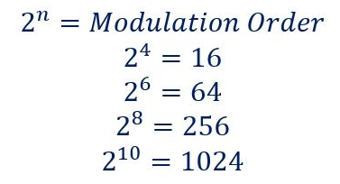
Modulation defines how many bits can be carried by a single RE irrespective of whether it’s useful bit or parity bits. 5G NR supports QPSK, 16 QAM, 64 QAM and 256 QAM modulation . With QPSK there are 2 bits can be transmitted per RE, with 16QAM it can be 4 bits, with 64QAM it can be 6 bits and with 256QAM it can 8 bits. These 16, 64 and 256 are know as modulation order of QAM Modulation and The no. of bits for each modulation order can be calculated using following formula.
Code Rate
Code rate can be defined as the ratio between useful bit and total transmitted bit (Useful + Redundant Bits). These Redundant bits are added for Forward Error Correction (FEC). In other words we can it is the ratio between the number of information bits at the top of the Physical layer and the number of bits which are mapped to PDSCH at the bottom of the Physical layer. We can also say, it a measure of the redundancy which is added by the Physical layer. A low coding rate corresponds to increased redundancy.
5G NR Modulation and Coding Scheme (MCS) Characteristics
Modulation and Coding Scheme (MCS) defines the numbers of useful bits per symbols
MCS selection is done based on radio condition and BLER
MCS is change by gNB based on link adaptation algorithm
MCS information is provided to UE using DCI
5G NR supports QPSK,16 QAM, 64 QAM and 256 QAM modulation for PDSCH
There are about 32 MCS Indexes (0-31) are defined and MCS Index 29,30 and 31 are reserved and used for re-transmission
3GPP Specification 38.214 has given three tables for PDSCH MCS namely 64 QAM Table, 256 QAM Table and Low Spectral Efficiency 64 QAM Table
Modulation and Coding Scheme Tables
64 QAM table may be used when gNB or UE is not supporting 256 QAM or in poor radio condition where 256 QAM table decoding is not successful and gNB needs to allocated QPSK order modulation
256 QAM table may be used whenever 256QAM is to be allocated in very good radio conditions
Low spectral efficiency (Low SE) 64 QAM table is suitable for applications which need reliable data transfer, e.g. applications belonging to the URLLC category. This table includes MCS which have low Spectral Efficiency i.e. a reduced coding rate which increase channel coding redundancy
64 QAM Table
256 QAM Table
Low SE 64 QAM Table
Which Table to select:
gNB instructs the UE to select a specific MCS table using a combination of RRC signalling (IEs) and Phy layer signalling (RNTI).
RRC signalling configure PDSCH-Config and SPS-Config parameter with the mcs-Table IE for a semi-static configuration which can be further modified using RRC signalling
Phy layer uses a dynamic selection of the RNTI which scrambles the CRC bits belonging to the PDCCH payload, e.g. switching between the C-RNTI and MCS-C-RNTI can influence the selection of the MCS table.
MCS Table Selection Example:
With this example, we can show that MCS table selection initially configured with RRC signaling and further can be controlled using only Physical layer signaling.
Consider a UE has been configured with parameter PDSCH-Config with mcs-Table= ‘qam256’ and allocated an MCS-C-RNTI alng with traditional a C-RNTI
If the UE receives a PDSCH resource allocation using DCI 1_ 1 with the C-RNTI, then the UE will select the 256 QAM MCS table
If the same UE receives a PDSCH resource allocation using DCT 1_ 0 with the C-RNTI, then UE will select the 64 QAM MCS table
If the same UE receives a PDSCH resource allocation using either DCI 1_ 1 or 1 _ 0 with the MCS-C-RNTI, then the UE will select the Low SE table.
Management, Orchestration and Charging for 5G networks
Key topics for modern 5G networks include Management, Orchestration and Charging. In December 2017, the 3GPP passed two major milestones for 5G by approving the first set of 5G NR specs and by putting in place the 5G Phase 1 System Architecture. These achievements have brought about the need for new management standards, as 5G adds to the ever-growing size and complexity of telecom systems.
3GPP management standards from working group SA5 are approaching another major milestone for 5G. With our studies on the 5G management architecture, network slicing and charging completed last year, we are now well under way with the normative work for the first phase in 3GPP Release 15, which includes building up a new service-oriented management architecture and all the necessary functionalities for management and charging for 5G networks.
SA5’s current work also includes several other work/study items such as management of QoE measurement collection and new technologies for RESTful management protocols. However, this article will focus on the new 5G Rel-15 architecture and the main functionalities, including charging.
5G networks and network slicing
Management and orchestration of 5G networks and network slicing is a feature that includes the following work items: management concept and architecture, provisioning, network resource model, fault supervision, assurance and performance management, trace management and virtualization management aspects. With the output of these work items, SA5 provides specified management interfaces in support of 5G networks and network slicing. An operator can configure and manage the mobile network to support various types of services enabled by 5G, for example eMBB (enhanced Mobile Broadband) and URLLC (Ultra-Reliable and Low Latency Communications), depending on the different customers’ needs. The management concept, architecture and provisioning are being defined in TS 28.530, 28.531, 28.532 and 28.533.
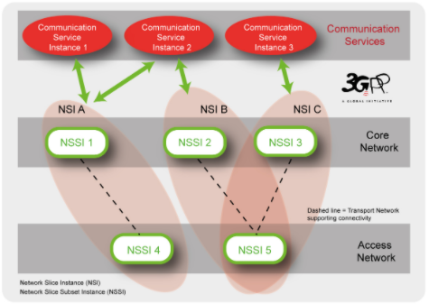
Network slicing is seen as one of the key features for 5G, allowing vertical industries to take advantage of 5G networks and services. 3GPP SA5 adopts the network slice concept as defined in SA2 and addresses the management aspects. Network slicing is about transforming a PLMN from a single network to a network where logical partitions are created, with appropriate network isolation, resources, optimized topology and specific configuration to serve various service requirements.
As an example, a variety of communication service instances provided by multiple Network Slice Instances (NSIs) are illustrated in the figure below. The different parts of an NSI are grouped as Network Slice Subnets (e.g. RAN, 5GC and Transport) allowing the lifecycle of a Network Slice Subnet Instance (NSSI) to be managed independently from the lifecycle of an NSI.
Provisioning of network slice instances
The management aspects of a network slice instance can be described by the four phases:
1) Preparation: in the preparation phase the network slice instance does not exist. The preparation phase includes network slice template design, network slice capacity planning, on-boarding and evaluation of the network slice requirements, preparing the network environment and other necessary preparations required to be done before the creation of a network slice instance.
2) Commissioning: provisioning in the commissioning phase includes creation of the network slice instance. During network slice instance creation all needed resources are allocated and configured to satisfy the network slice requirements. The creation of a network slice instance can include creation and/or modification of the network slice instance constituents.
3) Operation: includes the activation, supervision, performance reporting (e.g. for KPI monitoring), resource capacity planning, modification, and de-activation of a network slice instance. Provisioning in the operation phase involves activation, modification and de-activation of a network slice instance.
4) Decommissioning: network slice instance provisioning in the decommissioning phase includes decommissioning of non-shared constituents if required and removing the network slice instance specific configuration from the shared constituents. After the decommissioning phase, the network slice instance is terminated and does not exist anymore.
Similarly, provisioning for a network slice subnet instance (NSSI) includes the following operations:
Create an NSSI;
Activate an NSSI;
De-active an NSSI;
Modify an NSSI;
Terminate an NSSI.
Roles related to 5G networks and network slicing
The roles related to 5G networks and network slicing management include: Communication Service Customer, Communication Service Provider (CSP), Network Operator (NOP), Network Equipment Provider (NEP), Virtualization Infrastructure Service Provider (VISP), Data Centre Service Provider (DCSP), NFVI (Network Functions Virtualization Infrastructure) Supplier and Hardware Supplier.
Depending on actual scenarios:
Each role can be played by one or more organizations simultaneously;
An organization can play one or several roles simultaneously (for example, a company can play CSP and NOP roles simultaneously).
Management models for network slicing
Different management models can be used in the context of network slicing.
1) Network Slice as a Service (NSaaS): NSaaS can be offered by a CSP to its CSC in the form of a communication service. This service allows CSC to use and optionally manage the network slice instance. In turn, this CSC can play the role of CSP and offer their own services (e.g. communication services) on top of the network slice instance. The MNSI (Managed Network Slice Instance) in the figure represents a network slice instance and CS represents a communication service.
2) Network Slices as NOP internals: network slices are not part of the CSP service offering and hence are not visible to CSCs. However, the NOP, to provide support to communication services, may decide to deploy network slices, e.g. for internal network optimization purposes.
Management architecture
SA5 recognizes the need for automation of management by introducing new management functions such as a communication service management function (CSMF), network slice management function (NSMF) and a network slice subnet management function (NSSMF) to provide an appropriate abstraction level for automation.
The 3GPP SA5 management architecture will adopt a service-oriented management architecture which is described as interaction between management service consumer and management service provider. For example, a management service consumer can request operations from management service providers on fault supervision service, performance management service, provisioning service and notification service, etc.
Network Resource Model (NRM) for 5G networks and network slicing
To support management and orchestration of 5G networks, the Network Resource Model (NRM) representing the manageable aspects of 5G networks needs to be defined, according to 5G network specifications from other 3GPP working groups as well as considering requirements from 5G management architecture and operations.
The 5G NRM specifications family includes 4 specifications: TS 28.540 and TS 28.541 for NRM of NR and NG-RAN, TS 28.542 and TS 28.543 for NRM of 5G core network.
According to content categorization, 5G NRM specifications can be divided into 3 parts:
Requirements, also known as stage 1,
Information Model definitions also known as stage 2, and
Solution Set definitions also known as stage 3.
Identified in the specifications of 5G NRM requirements (TS 28.540 and TS 28.542), the NRM of 5G network comprises NRM for the 5G core network (5GC) and NRM for 5G radio access network (i.e. NR and NG-RAN). The 5GC NRM definitions support management of 5GC Network Functions, respective interfaces as well as AMF Set and AMF Region. The NR and NG-RAN NRM definitions cover various 5G radio networks connectivity options (standalone and non-standalone radio node deployment options) and architectural options (NR nodes with or without functional split).
The 5G Information Model definitions specify the semantics and behavior of information object class attributes and relations visible on the 5G management interfaces, in a protocol and technology neutral way (UML as protocol-neutral language is used). The 5G Information Model is defined according to 5GC, NR and NG-RAN specifications. For example, in 3GPP TS 38.401, the NR node (gNB) is defined to support three functional split options (i.e. non-split option, two split option with CU and DU, three split option with CU-CP, CU-UP and DU), so in the NR NRM Information Model, corresponding Information Object Class (IOC) is defined for each network function of gNB specified, and different UML diagrams show the relationship of each gNB split option respectively. Further, in the 5G Information Model definitions, the existing Generic NRM Information Service specification (TS 28.622) is referenced to inherit the attributes of generic information object classes, and the existing EPC NRM Information Service specification (TS 28.708) is referenced for 5GS / EPS interworking relationships description.
Finally, NRM Solution Set definitions map the Information Model definitions to a specific protocol definition used for implementations. According to recommendation from TR 32.866 (Study on RESTful based Solution Set), JSON is expected to be chosen as data modelling language to describe one 5G NRM Solution Set.
Fault Supervision of 5G networks and network slicing
Fault Supervision is one of the fundamental functions for the management of a 5G network and its communication services. For the fault supervision of 5G networks and network slicing, the following 3GPP TSs are being specified:
1) TS 28.545 “Management and orchestration of networks and network slicing; Fault Supervision (FS); Stage 1”, which includes:
The use cases and requirements for fault supervision of 5G networks and network slicing.
The definitions of fault supervision related management services (e.g. NetworkSliceAlarmAcknowledgement, NetworkSliceAlarmListReading, NetworkSliceAlarmClearance, NetworkSliceAlarmNotification, NetworkSliceAlarmSubscription, etc.)
2) TS 28.546 “Management and orchestration of networks and network slicing; Fault Supervision (FS); Stage 2 and stage 3”, which includes the definition of:
Interfaces of the fault supervision related management services; (Stage 2)
Notifications; (Stage 2)
Alarm related information models (e.g. alarmInformation, alarmList, etc.); (Stage 2)
Solution set(s) (e.g. RESTful HTTP-based solution set for Fault Supervison); (Stage 3)
New event types and probable causes if necessary.
Assurance data and Performance Management for 5G networks and network slicing
The 5G network is designed to accommodate continuously fast increasing data traffic demand, and in addition, to support new services such as IoT, cloud-based services, industrial control, autonomous driving, mission critical communications, etc. Such services may have their own performance criteria, such as massive connectivity, extreme broadband, ultra-low latency and ultra-high reliability.
The performance data of the 5G networks and NFs (Network Functions) are fundamental for network monitoring, assessment, analysis, optimization and assurance. For the services with ultra-low latency and ultra-high reliability requirements, any faults or performance issues in the networks can cause service failure which may result in serious personal and property losses. Therefore, it is necessary to be able to collect the performance data in real-time (e.g., by performance data streaming), so that the analytic applications (e.g., network optimization, SON, etc.) could use the performance data to detect any network performance problems, predict the potential issues and take appropriate actions quickly or even in advance.
For network slicing, the communication services are provided on top of the end-to-end network slice instances, so the performance needs to be monitored from end-to-end point of view.
The end to end performance data of 5G networks (including sub-networks), NSIs (Network Slice Instances) and NSSIs (Network Slice Subnet Instances) are vital for operators to know whether they can meet the communication service requirement.
The performance data may be used by various kinds of consumers, such as network operator, SON applications, network optimization applications, network analytics applications, performance assurance applications, etc. To facilitate various consumers to get their required performance data, the following items are being pursued by this WI:
A service based PM framework and a list of PM services as described in the table below:
Management service name
Management service description
NF measurement job control service
The management service for creating and terminating the measurement job(s) for the NF(s).
NF measurement job information service
The management service for querying the information of the measurement job(s) for the NF(s).
NF performance data file reporting Service
The management service for reporting the NF performance data file.
NF performance data streaming service
The management service for providing streaming of NF performance data.
NSSI measurement job control service
The management service for creating and terminating the measurement job(s) for the NSSI(s).
NSSI measurement job information service
The management service for querying the information of the measurement job(s) for the NSSI(s).
NSSI performance data file reporting Service
The management service for reporting the NSSI performance data file.
NSSI performance data streaming service
The management service for providing streaming of NSSI performance data.
NSI measurement job control service
The management service for creating and terminating the measurement job(s) for the NSI(s).
NSI measurement job information service
The management service for querying the information of the measurement job(s) for the NSI(s).
NSI performance data file reporting Service
The management service for reporting the NSI performance data file.
NSI performance data streaming service
The management service for providing streaming of NSI performance data.
Network measurement job control service
The management service for creating and terminating the measurement job(s) to collect the network performance data that is not specific to network slicing.
Network measurement job information service
The management service for querying the information of the measurement job(s) to collect the network performance data that is not specific to network slicing.
Network performance data file reporting service
The management service for reporting the network performance data file that is not specific to network slicing.
Network performance data streaming service
The management service for providing network performance data streaming that is not specific to network slicing.
Performance measurements (including the data that can be used for performance assurance) for 3GPP NFs;
End to end KPIs, performance measurements (including the data that can be used for performance assurance) for NSIs, NSSIs and networks (where the performance data is not specific to network slicing).
Management and virtualization aspects of 5G networks
For 5G networks, it is expected that most of the network functions will run as software components on operators’ telco-cloud systems rather than using dedicated hardware components. Besides the virtualization for Core Network (including 5GC, EPC and IMS), the NG-RAN architecture is being defined with functional split between central unit and distributed unit, where the central unit can also be virtualized.
SA5 has conducted a study on management aspects of the NG-RAN that includes virtualized network functions, and has concluded in TR 32.864 that the existing specifications (related to management of mobile networks that include virtualized network functions) need some enhancements for 5G. The enhancements are mainly on the interactions between 3GPP management system and external management systems (e.g., ETSI NFV MANO) for the following aspects:
Management requirements and architecture;
Life Cycle Management (e.g., PNF management);
Configuration Management;
Performance Management;
Fault Management.
There are gaps identified between 3GPP SA5 requirements and ETSI ISG NFV solutions in terms of the required enhancements, and 3GPP SA5 is in cooperation with ETSI ISG NFV to solve these gaps.
Although the need for enhancements were found in the study for 5G, SA5 has reached the conclusion that they can be the used for 4G as well. So the specifications for management of mobile networks that include virtualized network functions are being made generally applicable to both 4G and 5G networks.
Study on energy efficiency of 5G networks
Following the conclusions of the study on Energy Efficiency (EE) aspects in 3GPP Standards, TSG SA#75 recommended initiating further follow-up studies on a range of energy efficiency control related issues for 5G networks including the following aspects:
Definition and calculation of EE KPIs in 3GPP Systems
Energy Efficiency control in 3GPP Systems
Coordinated energy saving in RAN and other subsystem in 3GPP Systems
Power consumption reduction at the site level
Energy Efficiency in 3GPP systems with NFV
Energy Efficiency in Self-Organizing Networks (SON).
TR 32.972 (Study on system and functional aspects of energy efficiency in 5G networks) aims to:
Identify EE KPI definitions made by ETSI TC EE, ITU-T SG5, ETSI NFV ISG, etc., which are relevant for 5G networks, in addition to definitions made in SA TR 21.866. Such EE KPIs can be defined at various levels, incl. network and equipment levels (potentially, at virtualized network function and virtualized resource level), and per deployment scenario (dense urban, rural, etc.). With 5G, potentially, EE KPIs can be defined at network slice level;
Identify metrics to be defined by 3GPP so as to be able to calculate the above EE KPIs for 5G networks. Such metrics might relate to data volumes, coverage area or energy consumption;
Assess whether existing OA&M mechanisms enable to control and monitor the identified metrics. In particular, check if the IRP for the control and monitoring of Power, Energy and Environmental (PEE) parameters for Radio Access Networks (RAN) (TS 28.304, 28.305, 28.306) can be applied to 5G networks. If not, identify potential new OA&M mechanisms;
Elaborate further on the EE control framework defined in TR 21.866 and identify potential gaps with respect to existing management architectures, incl. SON and NFV based architectures;
Examine whether new energy saving functionalities might enable the 3GPP management system to manage energy more efficiently. In particular, the applicability of ETSI ES 203 237 (Green Abstraction Layer; Power management capabilities of the future energy telecommunication fixed network nodes) to the management of 5G networks is to be evaluated;
Identify potential enhancements in existing standards which could lead to achieving improved 3GPP system-wide energy efficiency.
This study requires interactions with other 3GPP working groups and SDOs working on related topics, including ITU-T SG5, ETSI TC EE, ETSI NFV ISG.
5G Charging system architecture and service based interface
Commercial deployment of the Rel-15 5G System will not be possible without capabilities for Operators to be able to monetize the various set of features and services which are specified in TS 23.501, TS 23.502 and TS 23.503. This is defined under the charging framework, which includes e.g. real-time control of subscriber’s usage of 5G Network resources for charging purpose, or per-UE data collection (e.g. for CDRs generation) which can also be used for other purposes e.g. analytics.
SA5 has investigated, during a study period in 2017, on how charging architecture should evolve, which key features should be specified as part of charging capabilities, and which alternative amongst charging solutions should be selected, to better support the first commercial 5G system deployment. Based on the study results, the charging architecture evolution and selected Rel-15 key functionalities for 5G system are under ongoing normative phase through development of a complete set of specifications (architecture, functionalities and protocols) A brief overview of the charging coverage for the Rel-15 5G system is provided in this article.
Service Based Interface
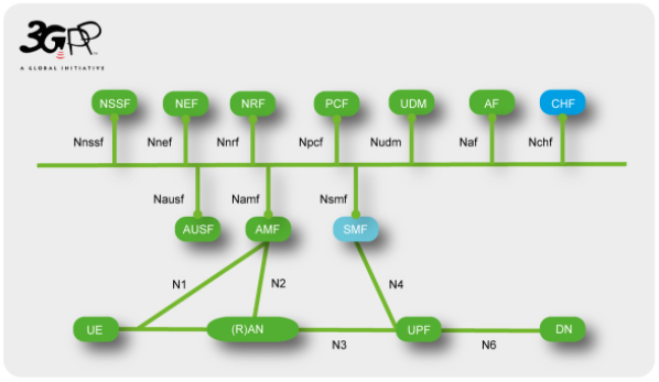
One key evolution of the charging architecture is the adoption of a service based interface integrated into the overall 5G system service based architecture, enabling deployments of charging functions in virtualized environment and use of new software techniques. The new charging function (CHF) introduced in the 5G system architecture, as shown in the picture below, allows charging services to be offered to authorized network functions. A converged online and offline charging will also be supported.
While offering the service based interface to the 5G system, the overall converged charging system will be able to interface the billing system as for the existing system (e.g. 4G) to allow Operators to preserve their billing environment. These evolutions are incorporated in the TS 32.240 umbrella architecture and principles charging specification. The services, operations and procedures of charging using Service Based Interface will be specified in a new TS 32.290, and TS 32.291 will be the stage 3 for this interface.
5G Data connectivity charging
The “5G Data connectivity charging”, achieved by SMF invocation of charging service(s) exposed by the charging function (CHF), will be specified in a new TS 32.255, encompassing the various configurations and functionalities supported via the SMF, which are highlighted below.
For 3GPP network deployments using network slicing, by indicating to the charging system which network slice instance is serving the UE during the data connectivity, the Operator will be able to apply business case charging differentiation. Further improvements on flexibility in charging systems deployments for 5G network slicing will be explored in future releases.
The new 5G QoS model introduced to support requirements from various applications in data connectivity, is considered to support QoS based charging for subscriber’s usage. 5G QoS-based charging is also defined to address inter-Operator’s settlements (i.e. between VPLMN and HPLMN) in roaming Home-routed scenario.
All charging aspects for data services in Local breakout roaming scenarios will be further considered.
In continuation with existing principles on Access type traffic charging differentiation, the two Access Networks (i.e. NG-RAN and untrusted WLAN access) supported in Rel-15 are covered.
Charging capabilities encompass the various functionalities introduced in the 5G system to support flexible deployment of application functions (e.g. edge computing), such as the three different Session and Service Continuity (SSC) modes and the Uplink Classifiers and Branching Points.
Charging continuity for interworking and handover between 5G and existing EPC is addressed.
In 5G Multi-Operator Core Network sharing architecture (i.e. shared RAN), identification of the PLMN that the 5G-RAN resources were used for to convey the traffic, allows settlements between Operators.
The stage 3 for “5G data connectivity charging” will be available in TS 32.298 for the CDRs’ ASN.1 definition and in TS 32.291 for the data type definition in the protocol used for the service based interface.
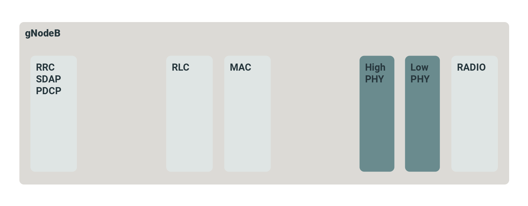
Functional Split Options for gNodeB 5G-NR Base Stations
A major benefit of 5G for Mobile Network Operators (MNOs) is the prospect of migrating from custom network nodes to a far more flexible approach that enables network nodes to be implemented in software running on generic hardware platforms. In the core network, this process is in an advanced state, with virtualisation and orchestration techniques from the IT world now being used to deploy network functions automatically at a large scale. The functional “split” is key to achieving efficiency gains.
The process is significantly more difficult in the RAN and backhaul network, and the prize for MNOs is greater here as these functions typically account for 70-80% of Capex. In Release 15, the 3GPP identified various functional splits in the 5G NR RAN gNodeB (base station) that would facilitate this process, identifying eight possible places where the gNodeB function could be split into separate functional units. The most popular of these “split” options are:
Split 0 – gNodeB Integrated Small Cell
The gNodeB is a traditional integrated 5G NR with the RF, PHY and stack layers integrated into a single unit, with an NG interface to the 5GC Core Network.
Split 2 – 3GPP F1
The 3GPP defines this disaggregated RAN with separate (gNodeB-)CU and (gNodeB-)DU units with a high level split 2 using the 3GPP defined F1 interface. Split 2 is sometimes used in conjunction with a lower level splits 6, 7.2 and 8. This new 3GPP 5G RAN architecture introduces new terminology, interfaces and functional modules.
Split 6 – Small Cell Forum (SCF) nFAPI
The split 6 interface protocol is the Network FAPI (nFAPI), specified by the Small Cell Forum, where the MAC and PHY functions are physically separate.
Split 7.2 – O-RAN Open Fronthaul
A split 7 interface has been specified by the O-RAN Alliance, which has adopted the eCPRI interface as its basis. Whereas CPRI passes antenna samples using a proprietary protocol, eCPRI uses Ethernet.
Split 8
The split 8 interface is mainly being considered where there are legacy systems and existing hardware and cabling/fibre can be reused.
Industry Body Backed Split Option Definitions
3GPP specified the higher layer F1 interface, but additional interfaces at lower layer splits have also been specified by other industry bodies, and offer different relative advantages and disadvantages.
The Split 6 interface protocol is the Network FAPI (nFAPI), specified by the Small Cell Forum, where the MAC and PHY functions are physically separate.
The Split 7 interface has been specified by the O-RAN Alliance, which has adopted the eCPRI interface as its basis. Whereas CPRI passes digitised RF signals to the antenna using a proprietary serial protocol, eCPRI uses Ethernet. Moreover, in O-RAN fronthaul, it is frequency domain samples that are transported between the upper PHY and lower PHY, which leads to advantages.
The Split 8 interface is mainly being considered where there are legacy systems and existing hardware and cabling/fibre can be reused.
We use technologies like cookies to store and/or access device information. We do this to improve browsing experience and to show personalized ads. Consenting to these technologies will allow us to process data such as browsing behavior or unique IDs on this site. Not consenting or withdrawing consent, may adversely affect certain features and functions.
Functional
Always active
The technical storage or access is strictly necessary for the legitimate purpose of enabling the use of a specific service explicitly requested by the subscriber or user, or for the sole purpose of carrying out the transmission of a communication over an electronic communications network.
Preferences
The technical storage or access is necessary for the legitimate purpose of storing preferences that are not requested by the subscriber or user.
Statistics
The technical storage or access that is used exclusively for statistical purposes.The technical storage or access that is used exclusively for anonymous statistical purposes. Without a subpoena, voluntary compliance on the part of your Internet Service Provider, or additional records from a third party, information stored or retrieved for this purpose alone cannot usually be used to identify you.
Marketing
The technical storage or access is required to create user profiles to send advertising, or to track the user on a website or across several websites for similar marketing purposes.