5G-NR Modulation and Coding as used by 5G Base Stations (gNodeb) and CPE devices:
For any communication technology, Modulation and Coding Scheme (MCS) defines the numbers of useful bits which can carried by one symbol. In contrast with 5G or 4G, a symbol is defined as Resource Element (RE) and MCS defined as how many useful bits can be transmitted per Resource Element (RE) . MCS depends on radio signal quality in wireless link, better quality the higher MCS and the more useful bits can be transmitted with in a symbol and bad signal quality result in lower MCS means less useful data can be transmitted with in a symbol.
In other words, we can say MCS depends Blocker Error Rate (BLER). Typically there is a BLER threshold defined that equal to 10%. To maintain BLER not more than this value in varying radio condition Modulation and Coding Scheme (MCS) is allocated by gNB using link adaptation algorithm. The allocated MCS is signalled to the UE using DCI over PDCCH channel e.g. DCI 1_0, DCI 1_1
A MCS basically defines the following two aspects:
Modulation
Code rate
Modulation
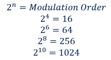
Modulation defines how many bits can be carried by a single RE irrespective of whether it’s useful bit or parity bits. 5G NR supports QPSK, 16 QAM, 64 QAM and 256 QAM modulation . With QPSK there are 2 bits can be transmitted per RE, with 16QAM it can be 4 bits, with 64QAM it can be 6 bits and with 256QAM it can 8 bits. These 16, 64 and 256 are know as modulation order of QAM Modulation and The no. of bits for each modulation order can be calculated using following formula.
Code Rate
Code rate can be defined as the ratio between useful bit and total transmitted bit (Useful + Redundant Bits). These Redundant bits are added for Forward Error Correction (FEC). In other words we can it is the ratio between the number of information bits at the top of the Physical layer and the number of bits which are mapped to PDSCH at the bottom of the Physical layer. We can also say, it a measure of the redundancy which is added by the Physical layer. A low coding rate corresponds to increased redundancy.
5G NR Modulation and Coding Scheme (MCS) Characteristics
Modulation and Coding Scheme (MCS) defines the numbers of useful bits per symbols
MCS selection is done based on radio condition and BLER
MCS is change by gNB based on link adaptation algorithm
MCS information is provided to UE using DCI
5G NR supports QPSK,16 QAM, 64 QAM and 256 QAM modulation for PDSCH
There are about 32 MCS Indexes (0-31) are defined and MCS Index 29,30 and 31 are reserved and used for re-transmission
3GPP Specification 38.214 has given three tables for PDSCH MCS namely 64 QAM Table, 256 QAM Table and Low Spectral Efficiency 64 QAM Table
Modulation and Coding Scheme Tables
64 QAM table may be used when gNB or UE is not supporting 256 QAM or in poor radio condition where 256 QAM table decoding is not successful and gNB needs to allocated QPSK order modulation
256 QAM table may be used whenever 256QAM is to be allocated in very good radio conditions
Low spectral efficiency (Low SE) 64 QAM table is suitable for applications which need reliable data transfer, e.g. applications belonging to the URLLC category. This table includes MCS which have low Spectral Efficiency i.e. a reduced coding rate which increase channel coding redundancy
64 QAM Table
256 QAM Table
Low SE 64 QAM Table
Which Table to select:
gNB instructs the UE to select a specific MCS table using a combination of RRC signalling (IEs) and Phy layer signalling (RNTI).
RRC signalling configure PDSCH-Config and SPS-Config parameter with the mcs-Table IE for a semi-static configuration which can be further modified using RRC signalling
Phy layer uses a dynamic selection of the RNTI which scrambles the CRC bits belonging to the PDCCH payload, e.g. switching between the C-RNTI and MCS-C-RNTI can influence the selection of the MCS table.
MCS Table Selection Example:
With this example, we can show that MCS table selection initially configured with RRC signaling and further can be controlled using only Physical layer signaling.
Consider a UE has been configured with parameter PDSCH-Config with mcs-Table= ‘qam256’ and allocated an MCS-C-RNTI alng with traditional a C-RNTI
If the UE receives a PDSCH resource allocation using DCI 1_ 1 with the C-RNTI, then the UE will select the 256 QAM MCS table
If the same UE receives a PDSCH resource allocation using DCT 1_ 0 with the C-RNTI, then UE will select the 64 QAM MCS table
If the same UE receives a PDSCH resource allocation using either DCI 1_ 1 or 1 _ 0 with the MCS-C-RNTI, then the UE will select the Low SE table.
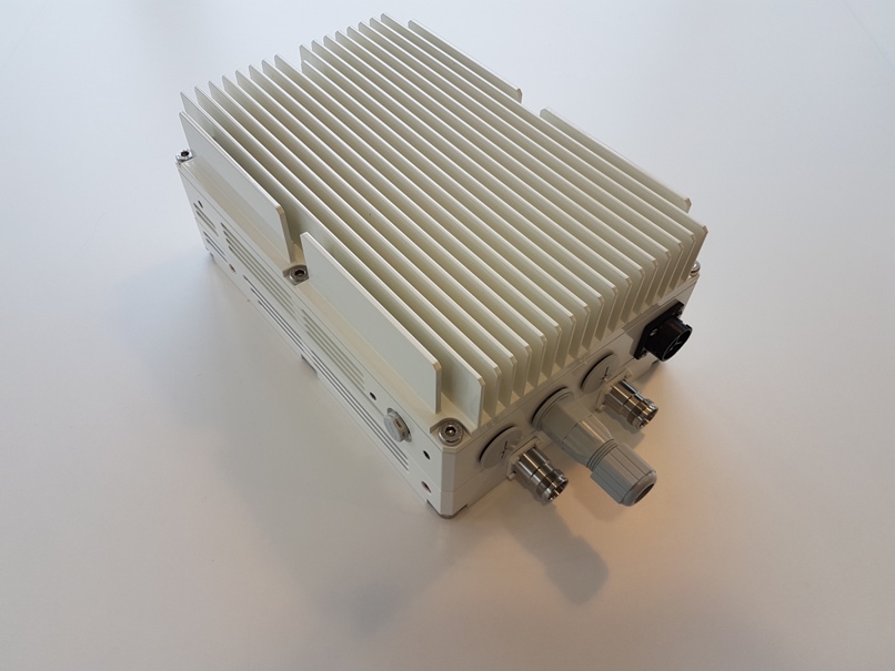
A 5G Remote Radio Head (RRH) comprises several key component parts. Here we look at some of the key technologies involved
5G Band n77 Remote Radio Head (RRH)
Remote Radio Head (RRH) Transceiver, (TRX)
In a modern RRH The Transceiver module may be a single high density PCB containing high speed logic, RF, slow speed analogue and management functions.
The RF processing stages will include complex technologies such as Digital Predistortion (DPD) and Crest Factor Reduction (CFR) which are key to ensure high fidelity of transmitted signals across the airside interface.
The high speed logic may be implemented in a Field Programmable Gate Array (FPGA).
High speed interfaces may include CPRI and/or 10Gbps Ethernet (IP) eCPRI interfaces. More modern Open RAN (ORAN) and Virtualised RAN (VRAN) networks require Ethernet interfaces and more complexity inside the RRH.
Lower speed interfaces may be used to control antenna arrays and other functions.
Front End Module (FEM)
An FEM is used in TDD variants as a highly integrated module. The Front End Module (FEM) contains the following key elements:
Power Amplifier (PA)
Low Noise Amplifier (LNA)
Transmit-Receive switch
FEM Model variants used in Remote Radio Heads to cover different frequency bands and power levels. Please note this is only a partial list of examples:
The Power Amplifier takes signals from the Transceiver (TRX) and boosts to high power levels needed for over-the-air transmission. The output power may vary from 100mW up to 80W per chain (channel) depending on the specific model and application.
Low Noise Amplifier (LNA)
The Low Noise Amplifier (LNA) takes low level input signals from the antenna and boosts them to suitable levels to feed to the Transceiver (TRX) module. The LNA must be suitable shielded to prevent unwanted signals entering, including from other items within the RRH.
RF Duplexer or Filter
Depending whether the RRH is being used in FDD or TDD mode, an RF Duplexer or Filter is used. TDD units feature a filter, and FDD units feature a Diplexer
This RF stage is key to remove unwanted harmonics from the transmission, and also block any unwanted signals from adjacent bands entering the sensitive RF receiver
DC-DC Power Supply (PSU)
The DC-DC Power Supply (PSU) takes input power (typically 36-72V, nominally 48V DC) and converts to smooth, stable power voltage rails to power the key items within the Remote Radio Head.
For Further Information on Remote Radio Head (RRH) technology:
CPRI, or Common Public Radio Interface, defines key interface specification between REC (Radio Equipment Control) and RE (Radio Equipment) of radio base stations used for cellular wireless networks. It is a protocol of choice for fronthaul communications between towers and base stations (BSs) through several generations of wireless networks. CPRI has efficient and flexible I/Q data interfaces for various standards, such as GSM, WCDMA, LTE, etc.
CPRI for 5G: Common Public Radio Interface
CPRI defines key interface specification between REC (Radio Equipment Control) and RE (Radio Equipment) of radio base stations used for cellular wireless networks. CPRI is the short form of Common Public Radio Interface. CPRI is popular standard for transporting baseband I/Q signals to the radio unit in traditional BS (Base Station). CPRI allows efficient and flexible I/Q data interface for various standards e.g. GSM, WCDMA, LTE etc.
eCPRI for 5G: Enhanced Common Public Radio Interface
eCPRI was created and published after CPRI. The eCPRI standard defines specification which connects eREC and eRE via fronthaul transport network. It is used for 5G systems, LTE-Advanced and LTE-Advanced Pro.
The Purpose of development of CPRI and eCPRI is as follows. Radio BSs should offer flexibility during deployment to MNOs( mobile network operators). This is achieved by simplifying BS architecture by dividing radio BS functionality into two modules viz. eREC and eRE. Both parts may be physically separated where in eRE is kept close to RF antenna where as eREC kept at a distant end. Both are connected via a transport network. The eREC contains part of PHY layer functions and upper layer functions of the air interface whereas eRE contains the other part of the PHY layer functions and the analog radio frequency (ARF) functions. The different functions can be located either in the eREC or in the eRE.
Interfaces used for Fronthaul in 4G and 5G Wireless Networks
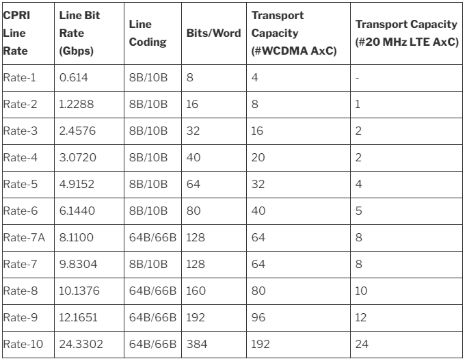
Both CPRI and eCPRI can be used in 5G fronthaul. While, eCPRI is more suitable in 5G fronthaul. Here are the network line rates:
CPRI Line Rate
Line Bit Rate (Gbps)
Line Coding
Bits/Word
Transport Capacity (#WCDMA AxC)
Transport Capacity (#20 MHz LTE AxC)
Rate-1
0.614
8B/10B
8
4
–
Rate-2
1.2288
8B/10B
16
8
1
Rate-3
2.4576
8B/10B
32
16
2
Rate-4
3.0720
8B/10B
40
20
2
Rate-5
4.9152
8B/10B
64
32
4
Rate-6
6.1440
8B/10B
80
40
5
Rate-7A
8.1100
64B/66B
128
64
8
Rate-7
9.8304
8B/10B
128
64
8
Rate-8
10.1376
64B/66B
160
80
10
Rate-9
12.1651
64B/66B
192
96
12
Rate-10
24.3302
64B/66B
384
192
24
CPRI line rates used in 4G and 5G
This table shows the different transport capacity at different line rates. Since 5G requires tremendous bandwidth expansion, line rate option 10, the newest standard, can meet latest 5G requirements. However, this processing capacity has reached the upper limit of the standard, causing doubt about whether 5G can be used with CPRI for future expansion.
Management, Orchestration and Charging for 5G networks
Key topics for modern 5G networks include Management, Orchestration and Charging. In December 2017, the 3GPP passed two major milestones for 5G by approving the first set of 5G NR specs and by putting in place the 5G Phase 1 System Architecture. These achievements have brought about the need for new management standards, as 5G adds to the ever-growing size and complexity of telecom systems.
3GPP management standards from working group SA5 are approaching another major milestone for 5G. With our studies on the 5G management architecture, network slicing and charging completed last year, we are now well under way with the normative work for the first phase in 3GPP Release 15, which includes building up a new service-oriented management architecture and all the necessary functionalities for management and charging for 5G networks.
SA5’s current work also includes several other work/study items such as management of QoE measurement collection and new technologies for RESTful management protocols. However, this article will focus on the new 5G Rel-15 architecture and the main functionalities, including charging.
5G networks and network slicing
Management and orchestration of 5G networks and network slicing is a feature that includes the following work items: management concept and architecture, provisioning, network resource model, fault supervision, assurance and performance management, trace management and virtualization management aspects. With the output of these work items, SA5 provides specified management interfaces in support of 5G networks and network slicing. An operator can configure and manage the mobile network to support various types of services enabled by 5G, for example eMBB (enhanced Mobile Broadband) and URLLC (Ultra-Reliable and Low Latency Communications), depending on the different customers’ needs. The management concept, architecture and provisioning are being defined in TS 28.530, 28.531, 28.532 and 28.533.
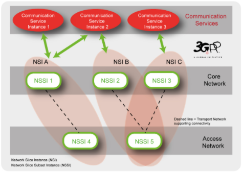
Network slicing is seen as one of the key features for 5G, allowing vertical industries to take advantage of 5G networks and services. 3GPP SA5 adopts the network slice concept as defined in SA2 and addresses the management aspects. Network slicing is about transforming a PLMN from a single network to a network where logical partitions are created, with appropriate network isolation, resources, optimized topology and specific configuration to serve various service requirements.
As an example, a variety of communication service instances provided by multiple Network Slice Instances (NSIs) are illustrated in the figure below. The different parts of an NSI are grouped as Network Slice Subnets (e.g. RAN, 5GC and Transport) allowing the lifecycle of a Network Slice Subnet Instance (NSSI) to be managed independently from the lifecycle of an NSI.
Provisioning of network slice instances
The management aspects of a network slice instance can be described by the four phases:
1) Preparation: in the preparation phase the network slice instance does not exist. The preparation phase includes network slice template design, network slice capacity planning, on-boarding and evaluation of the network slice requirements, preparing the network environment and other necessary preparations required to be done before the creation of a network slice instance.
2) Commissioning: provisioning in the commissioning phase includes creation of the network slice instance. During network slice instance creation all needed resources are allocated and configured to satisfy the network slice requirements. The creation of a network slice instance can include creation and/or modification of the network slice instance constituents.
3) Operation: includes the activation, supervision, performance reporting (e.g. for KPI monitoring), resource capacity planning, modification, and de-activation of a network slice instance. Provisioning in the operation phase involves activation, modification and de-activation of a network slice instance.
4) Decommissioning: network slice instance provisioning in the decommissioning phase includes decommissioning of non-shared constituents if required and removing the network slice instance specific configuration from the shared constituents. After the decommissioning phase, the network slice instance is terminated and does not exist anymore.
Similarly, provisioning for a network slice subnet instance (NSSI) includes the following operations:
Create an NSSI;
Activate an NSSI;
De-active an NSSI;
Modify an NSSI;
Terminate an NSSI.
Roles related to 5G networks and network slicing
The roles related to 5G networks and network slicing management include: Communication Service Customer, Communication Service Provider (CSP), Network Operator (NOP), Network Equipment Provider (NEP), Virtualization Infrastructure Service Provider (VISP), Data Centre Service Provider (DCSP), NFVI (Network Functions Virtualization Infrastructure) Supplier and Hardware Supplier.
Depending on actual scenarios:
Each role can be played by one or more organizations simultaneously;
An organization can play one or several roles simultaneously (for example, a company can play CSP and NOP roles simultaneously).
Management models for network slicing
Different management models can be used in the context of network slicing.
1) Network Slice as a Service (NSaaS): NSaaS can be offered by a CSP to its CSC in the form of a communication service. This service allows CSC to use and optionally manage the network slice instance. In turn, this CSC can play the role of CSP and offer their own services (e.g. communication services) on top of the network slice instance. The MNSI (Managed Network Slice Instance) in the figure represents a network slice instance and CS represents a communication service.
2) Network Slices as NOP internals: network slices are not part of the CSP service offering and hence are not visible to CSCs. However, the NOP, to provide support to communication services, may decide to deploy network slices, e.g. for internal network optimization purposes.
Management architecture
SA5 recognizes the need for automation of management by introducing new management functions such as a communication service management function (CSMF), network slice management function (NSMF) and a network slice subnet management function (NSSMF) to provide an appropriate abstraction level for automation.
The 3GPP SA5 management architecture will adopt a service-oriented management architecture which is described as interaction between management service consumer and management service provider. For example, a management service consumer can request operations from management service providers on fault supervision service, performance management service, provisioning service and notification service, etc.
Network Resource Model (NRM) for 5G networks and network slicing
To support management and orchestration of 5G networks, the Network Resource Model (NRM) representing the manageable aspects of 5G networks needs to be defined, according to 5G network specifications from other 3GPP working groups as well as considering requirements from 5G management architecture and operations.
The 5G NRM specifications family includes 4 specifications: TS 28.540 and TS 28.541 for NRM of NR and NG-RAN, TS 28.542 and TS 28.543 for NRM of 5G core network.
According to content categorization, 5G NRM specifications can be divided into 3 parts:
Requirements, also known as stage 1,
Information Model definitions also known as stage 2, and
Solution Set definitions also known as stage 3.
Identified in the specifications of 5G NRM requirements (TS 28.540 and TS 28.542), the NRM of 5G network comprises NRM for the 5G core network (5GC) and NRM for 5G radio access network (i.e. NR and NG-RAN). The 5GC NRM definitions support management of 5GC Network Functions, respective interfaces as well as AMF Set and AMF Region. The NR and NG-RAN NRM definitions cover various 5G radio networks connectivity options (standalone and non-standalone radio node deployment options) and architectural options (NR nodes with or without functional split).
The 5G Information Model definitions specify the semantics and behavior of information object class attributes and relations visible on the 5G management interfaces, in a protocol and technology neutral way (UML as protocol-neutral language is used). The 5G Information Model is defined according to 5GC, NR and NG-RAN specifications. For example, in 3GPP TS 38.401, the NR node (gNB) is defined to support three functional split options (i.e. non-split option, two split option with CU and DU, three split option with CU-CP, CU-UP and DU), so in the NR NRM Information Model, corresponding Information Object Class (IOC) is defined for each network function of gNB specified, and different UML diagrams show the relationship of each gNB split option respectively. Further, in the 5G Information Model definitions, the existing Generic NRM Information Service specification (TS 28.622) is referenced to inherit the attributes of generic information object classes, and the existing EPC NRM Information Service specification (TS 28.708) is referenced for 5GS / EPS interworking relationships description.
Finally, NRM Solution Set definitions map the Information Model definitions to a specific protocol definition used for implementations. According to recommendation from TR 32.866 (Study on RESTful based Solution Set), JSON is expected to be chosen as data modelling language to describe one 5G NRM Solution Set.
Fault Supervision of 5G networks and network slicing
Fault Supervision is one of the fundamental functions for the management of a 5G network and its communication services. For the fault supervision of 5G networks and network slicing, the following 3GPP TSs are being specified:
1) TS 28.545 “Management and orchestration of networks and network slicing; Fault Supervision (FS); Stage 1”, which includes:
The use cases and requirements for fault supervision of 5G networks and network slicing.
The definitions of fault supervision related management services (e.g. NetworkSliceAlarmAcknowledgement, NetworkSliceAlarmListReading, NetworkSliceAlarmClearance, NetworkSliceAlarmNotification, NetworkSliceAlarmSubscription, etc.)
2) TS 28.546 “Management and orchestration of networks and network slicing; Fault Supervision (FS); Stage 2 and stage 3”, which includes the definition of:
Interfaces of the fault supervision related management services; (Stage 2)
Notifications; (Stage 2)
Alarm related information models (e.g. alarmInformation, alarmList, etc.); (Stage 2)
Solution set(s) (e.g. RESTful HTTP-based solution set for Fault Supervison); (Stage 3)
New event types and probable causes if necessary.
Assurance data and Performance Management for 5G networks and network slicing
The 5G network is designed to accommodate continuously fast increasing data traffic demand, and in addition, to support new services such as IoT, cloud-based services, industrial control, autonomous driving, mission critical communications, etc. Such services may have their own performance criteria, such as massive connectivity, extreme broadband, ultra-low latency and ultra-high reliability.
The performance data of the 5G networks and NFs (Network Functions) are fundamental for network monitoring, assessment, analysis, optimization and assurance. For the services with ultra-low latency and ultra-high reliability requirements, any faults or performance issues in the networks can cause service failure which may result in serious personal and property losses. Therefore, it is necessary to be able to collect the performance data in real-time (e.g., by performance data streaming), so that the analytic applications (e.g., network optimization, SON, etc.) could use the performance data to detect any network performance problems, predict the potential issues and take appropriate actions quickly or even in advance.
For network slicing, the communication services are provided on top of the end-to-end network slice instances, so the performance needs to be monitored from end-to-end point of view.
The end to end performance data of 5G networks (including sub-networks), NSIs (Network Slice Instances) and NSSIs (Network Slice Subnet Instances) are vital for operators to know whether they can meet the communication service requirement.
The performance data may be used by various kinds of consumers, such as network operator, SON applications, network optimization applications, network analytics applications, performance assurance applications, etc. To facilitate various consumers to get their required performance data, the following items are being pursued by this WI:
A service based PM framework and a list of PM services as described in the table below:
Management service name
Management service description
NF measurement job control service
The management service for creating and terminating the measurement job(s) for the NF(s).
NF measurement job information service
The management service for querying the information of the measurement job(s) for the NF(s).
NF performance data file reporting Service
The management service for reporting the NF performance data file.
NF performance data streaming service
The management service for providing streaming of NF performance data.
NSSI measurement job control service
The management service for creating and terminating the measurement job(s) for the NSSI(s).
NSSI measurement job information service
The management service for querying the information of the measurement job(s) for the NSSI(s).
NSSI performance data file reporting Service
The management service for reporting the NSSI performance data file.
NSSI performance data streaming service
The management service for providing streaming of NSSI performance data.
NSI measurement job control service
The management service for creating and terminating the measurement job(s) for the NSI(s).
NSI measurement job information service
The management service for querying the information of the measurement job(s) for the NSI(s).
NSI performance data file reporting Service
The management service for reporting the NSI performance data file.
NSI performance data streaming service
The management service for providing streaming of NSI performance data.
Network measurement job control service
The management service for creating and terminating the measurement job(s) to collect the network performance data that is not specific to network slicing.
Network measurement job information service
The management service for querying the information of the measurement job(s) to collect the network performance data that is not specific to network slicing.
Network performance data file reporting service
The management service for reporting the network performance data file that is not specific to network slicing.
Network performance data streaming service
The management service for providing network performance data streaming that is not specific to network slicing.
Performance measurements (including the data that can be used for performance assurance) for 3GPP NFs;
End to end KPIs, performance measurements (including the data that can be used for performance assurance) for NSIs, NSSIs and networks (where the performance data is not specific to network slicing).
Management and virtualization aspects of 5G networks
For 5G networks, it is expected that most of the network functions will run as software components on operators’ telco-cloud systems rather than using dedicated hardware components. Besides the virtualization for Core Network (including 5GC, EPC and IMS), the NG-RAN architecture is being defined with functional split between central unit and distributed unit, where the central unit can also be virtualized.
SA5 has conducted a study on management aspects of the NG-RAN that includes virtualized network functions, and has concluded in TR 32.864 that the existing specifications (related to management of mobile networks that include virtualized network functions) need some enhancements for 5G. The enhancements are mainly on the interactions between 3GPP management system and external management systems (e.g., ETSI NFV MANO) for the following aspects:
Management requirements and architecture;
Life Cycle Management (e.g., PNF management);
Configuration Management;
Performance Management;
Fault Management.
There are gaps identified between 3GPP SA5 requirements and ETSI ISG NFV solutions in terms of the required enhancements, and 3GPP SA5 is in cooperation with ETSI ISG NFV to solve these gaps.
Although the need for enhancements were found in the study for 5G, SA5 has reached the conclusion that they can be the used for 4G as well. So the specifications for management of mobile networks that include virtualized network functions are being made generally applicable to both 4G and 5G networks.
Study on energy efficiency of 5G networks
Following the conclusions of the study on Energy Efficiency (EE) aspects in 3GPP Standards, TSG SA#75 recommended initiating further follow-up studies on a range of energy efficiency control related issues for 5G networks including the following aspects:
Definition and calculation of EE KPIs in 3GPP Systems
Energy Efficiency control in 3GPP Systems
Coordinated energy saving in RAN and other subsystem in 3GPP Systems
Power consumption reduction at the site level
Energy Efficiency in 3GPP systems with NFV
Energy Efficiency in Self-Organizing Networks (SON).
TR 32.972 (Study on system and functional aspects of energy efficiency in 5G networks) aims to:
Identify EE KPI definitions made by ETSI TC EE, ITU-T SG5, ETSI NFV ISG, etc., which are relevant for 5G networks, in addition to definitions made in SA TR 21.866. Such EE KPIs can be defined at various levels, incl. network and equipment levels (potentially, at virtualized network function and virtualized resource level), and per deployment scenario (dense urban, rural, etc.). With 5G, potentially, EE KPIs can be defined at network slice level;
Identify metrics to be defined by 3GPP so as to be able to calculate the above EE KPIs for 5G networks. Such metrics might relate to data volumes, coverage area or energy consumption;
Assess whether existing OA&M mechanisms enable to control and monitor the identified metrics. In particular, check if the IRP for the control and monitoring of Power, Energy and Environmental (PEE) parameters for Radio Access Networks (RAN) (TS 28.304, 28.305, 28.306) can be applied to 5G networks. If not, identify potential new OA&M mechanisms;
Elaborate further on the EE control framework defined in TR 21.866 and identify potential gaps with respect to existing management architectures, incl. SON and NFV based architectures;
Examine whether new energy saving functionalities might enable the 3GPP management system to manage energy more efficiently. In particular, the applicability of ETSI ES 203 237 (Green Abstraction Layer; Power management capabilities of the future energy telecommunication fixed network nodes) to the management of 5G networks is to be evaluated;
Identify potential enhancements in existing standards which could lead to achieving improved 3GPP system-wide energy efficiency.
This study requires interactions with other 3GPP working groups and SDOs working on related topics, including ITU-T SG5, ETSI TC EE, ETSI NFV ISG.
5G Charging system architecture and service based interface
Commercial deployment of the Rel-15 5G System will not be possible without capabilities for Operators to be able to monetize the various set of features and services which are specified in TS 23.501, TS 23.502 and TS 23.503. This is defined under the charging framework, which includes e.g. real-time control of subscriber’s usage of 5G Network resources for charging purpose, or per-UE data collection (e.g. for CDRs generation) which can also be used for other purposes e.g. analytics.
SA5 has investigated, during a study period in 2017, on how charging architecture should evolve, which key features should be specified as part of charging capabilities, and which alternative amongst charging solutions should be selected, to better support the first commercial 5G system deployment. Based on the study results, the charging architecture evolution and selected Rel-15 key functionalities for 5G system are under ongoing normative phase through development of a complete set of specifications (architecture, functionalities and protocols) A brief overview of the charging coverage for the Rel-15 5G system is provided in this article.
Service Based Interface
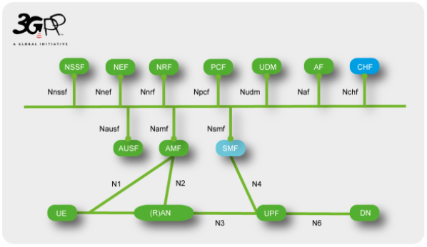
One key evolution of the charging architecture is the adoption of a service based interface integrated into the overall 5G system service based architecture, enabling deployments of charging functions in virtualized environment and use of new software techniques. The new charging function (CHF) introduced in the 5G system architecture, as shown in the picture below, allows charging services to be offered to authorized network functions. A converged online and offline charging will also be supported.
While offering the service based interface to the 5G system, the overall converged charging system will be able to interface the billing system as for the existing system (e.g. 4G) to allow Operators to preserve their billing environment. These evolutions are incorporated in the TS 32.240 umbrella architecture and principles charging specification. The services, operations and procedures of charging using Service Based Interface will be specified in a new TS 32.290, and TS 32.291 will be the stage 3 for this interface.
5G Data connectivity charging
The “5G Data connectivity charging”, achieved by SMF invocation of charging service(s) exposed by the charging function (CHF), will be specified in a new TS 32.255, encompassing the various configurations and functionalities supported via the SMF, which are highlighted below.
For 3GPP network deployments using network slicing, by indicating to the charging system which network slice instance is serving the UE during the data connectivity, the Operator will be able to apply business case charging differentiation. Further improvements on flexibility in charging systems deployments for 5G network slicing will be explored in future releases.
The new 5G QoS model introduced to support requirements from various applications in data connectivity, is considered to support QoS based charging for subscriber’s usage. 5G QoS-based charging is also defined to address inter-Operator’s settlements (i.e. between VPLMN and HPLMN) in roaming Home-routed scenario.
All charging aspects for data services in Local breakout roaming scenarios will be further considered.
In continuation with existing principles on Access type traffic charging differentiation, the two Access Networks (i.e. NG-RAN and untrusted WLAN access) supported in Rel-15 are covered.
Charging capabilities encompass the various functionalities introduced in the 5G system to support flexible deployment of application functions (e.g. edge computing), such as the three different Session and Service Continuity (SSC) modes and the Uplink Classifiers and Branching Points.
Charging continuity for interworking and handover between 5G and existing EPC is addressed.
In 5G Multi-Operator Core Network sharing architecture (i.e. shared RAN), identification of the PLMN that the 5G-RAN resources were used for to convey the traffic, allows settlements between Operators.
The stage 3 for “5G data connectivity charging” will be available in TS 32.298 for the CDRs’ ASN.1 definition and in TS 32.291 for the data type definition in the protocol used for the service based interface.
Virtualised and Disaggregated 5G vRAN Architecture Overview : Futureproof vRAN architecture for Next Generation 5G networks
Now in the 5G era, a wide variety of new technologies and services is being introduced. These include LTE-NR Dual Connectivity (EN-DC), NR-NR Dual Connectivity (NR-DC), millimeter wave (mmWave) spectrum, Network Function Virtualisation (NFV), Containerised Network Functions, massive Machine Type Communications (mMTC), Ultra Reliable Low Latency Communication (URLLC), Multi-Access Edge Computing (MEC), Network Slicing and Vertical Services, just to name a few. Here we consider vRAN:
Conventional access systems provide a static network architecture which suffers from some fairly challenging limitations in terms of supporting many of these technologies and services. Consequently, a new 5G access system architecture, referred to as ‘Disaggregated RAN’, aims to overcome many of these challenges by breaking up monolithic network features into smaller components that can be individually re-located as needed without hindering their ability to work together to provide network services. Virtualisation, on the other hand, transitions each of these functions from dedicated hardware to software components, allowing for flexible scaling, as well as rapid and continuous evolution, so that networks can meet the evolving demands of new and existing services with minimal impact to CAPEX and OPEX. The new 5G access system architecture has four distinct characteristics which will be described in the following section along with the benefits provided in comparison with legacy hardware solutions. I.e., CU (Central Unit) / DU (Distributed Unit) split, CU-CP (Control Plane) / CU-UP (User Plane) split, CU virtualisation and DU virtualisation.
Virtualised and disaggregated RAN architecture
1 CU/DU Split Architecture
The gNB is split into a CU and DU for the scalability and DU offloading
In order to overcome an explosion in traffic usage, 5G largely makes use of higher frequency bands than LTE. Doing so introduces challenges in coverage due to the inverse relationship between frequency and cell coverage. Typically, small coverage cells result in more frequent handovers for mobile users and this risks impacting quality of experience if not appropriately managed. If we can increase the number of cells being managed by each individual base station (gNB), then a greater number of handovers can be handled through intra-gNB mobility which has a significantly smaller impact than inter-gNB mobility since the device’s anchor point remains the same. By separating this functionality from the Digital Unit (DU) and centralizing it towards the Central Unit (CU), we can increase the number of cells being managed by each CU, and thus maximize the ratio of intra- vs inter-gNB handovers. At the same time, higher frequency bands also allow the use of wider bandwidth carriers and thus gNBs need considerably more traffic processing capacity compared to LTE eNBs. Compounding on this, when Dual Connectivity is widely used in 5G networks, devices may connect to two different gNBs, but only one of these (the anchor DU) is responsible for processing the split data streams (via Packet Data Convergence Protocol, or PDCP). Thus the PDCP load is concentrated on the PDCP anchor DU, which creates a load imbalance and inefficient resource usage between the PDCP anchor DU (over-utilised) and the non-anchor DU (under-utilised). To mitigate this load imbalance, PDCP aggregation needs to be off-loaded to the CU in a more central site where pooling /resource sharing can efficiently handle the task. For these reasons, 5G deployments are best served by a separated CU that is more centrally located from the DU.
vRAN CU (Central Unit)
● Non-Real time processing such as RRC, PDCP is off-loaded to the central site and the RRC, PDCP resource pool is shared between multiple DUs. ● CU can accommodate multiple DUs to build a large scale gNB. ● CU is typically virtualised on a COTS server for the scalability and flexibility.
vRAN DU (Distributed Unit)
● Real time processing such as RLC, MAC, PHY, RF need to remain close to the local site. ● DU is also virtualised on a COTS server for business agility.
2 CU-CP/CU-UP Split Architecture
The gNB-CU is split into CP and UP for flexible dimensioning and topology
The new 5G services based around massive Machine Type Communications (mMTC), Ultra Reliable and Low Latency Communications (URLLC), Fixed Wireless Access (FWA), and new industry verticals will generate unique traffic patterns compared to typical mobile data service. The Conventional DUs with fixed Control and User Plane (CU/UP) resources, which are typically designed to accommodate such ‘typical mobile data services’, are not well-suited to support the newer traffic patterns. Instead, a more flexible capability to dimension and scale directly in-line the traffic requirements of new types of services is needed. In particular, as Network Slicing and MEC are introduced, the UP should be divisible into multiple entities and allocated wherever needed for optimization of each specific services.
CU-CP/CU-UP split architecture
3 CU/DU Virtualisation
The CU and DU are virtualised for the enhanced scalability, flexibility and resource efficiency Along withthe CU/DU split and CU-CP/CU-UP split, container technology can further enhance scalability, flexibility and resource efficiency.
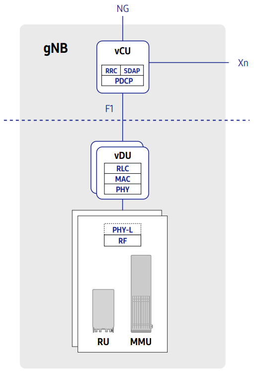
3-1 CU Virtualisation Each component in the vCU can have its own flavour (size) for flexible dimensioning. Traffic loads for control and user planes are balanced between each plane’s components separately to maximize resource usage efficiency. Each component can be scaled on-demand or automatically based on current load status. 3-2 DU Virtualisation Each component in the vDU can have its own flavour (size) for flexible dimensioning. DU components can be scaled out if additional cells are deployed.
CU Virtualisation architectureDU Virtualisation architecture
Benefits of Virtualised and Disaggregated RAN Architecture
Network evolution through Software upgrade
In traditional, hardware-oriented network solutions, the deployment of new standards, features and services often requires replacement of hardware, particularly when there are changes to lower layer protocols or when there is a need for increased processing capacity. With Virtualisation of the RAN, in which L1/L2 functions are implemented purely through software, the expensive and time- consuming process of hardware replacement can be avoided. Furthermore, as capacity requirements grow due to increased traffic demand, generic off-the-shelf compute hardware can be added to the resource pool – a much more cost-effective proposition than swapping older proprietary hardware for newer proprietary hardware. The end result is that operators are better able to manage and maximize the lifecycle of their hardware, match forecasted growth to CAPEX and reduce overall costs of ownership.
Adoption of well-developed IT technologies
By implementation of Network Function Virtualisation, operators can deploy and manage their network utilizing well -developed IT principles such as Software-Defined Networking, life-cycle management and CI/CD to minimize CAPEX and OPEX.
Scalable gNB beyond DU boundary
With a CU/DU split, the gNB can be scaled flexibly from small (single DU size) to large (accommodating multiple DUs, up to 2048 cells), agnostic of DU hardware types for various deployment environment (e.g. rural, dense urban, D-RAN, C-RAN, Small Cell, mmWave). This is in contrast to the conventional DU architecture, which presents limitations on gNB scale based on the capacity of individual DU hardware.
Mobility optimised vRAN architecture
In a conventional aggregated RAN, as users move around the boundary of different cells being served by different gNBs, service quality can often be degraded due to frequent inter-gNB handovers and packet forwarding between DUs. On the other hand, each CU in a disaggregated RAN can accommodate a much larger number of cells for each gNB, and itself becomes the mobility anchor point, greatly reducing the number of anchor point handovers that occur as users move between cells. For users, the key benefit is a noticeably improved quality of experience and more reliable mobility as inter-gNB handovers and packet forwarding is reduced within the broader CU coverage footprint. When UE moves to neighbor cell, intra-gNB HO of CU/DU split architecture has no RRC/PDCP anchor change, no traffic forwarding during HO procedure and no HO signaling toward the Core Networks compared to inter-gNB HO of conventional DU architecture.
Mobility optimised architecture
Flexibility in CU-UP deployment
The user plane of CU can be sliced into multiple CU-UPs to support network slicing and multiple CU-UPs can be deployed in independent locations while single CU-CP is deployed in the central site. For the network slicing and MEC scenarios such as low latency services or local-break out applications, CU-UP can be located close to DU while CU-UP for eMBB service remains in central site for the high capacity.
Flexibility in CU-IP deployment
CP/UP independent dimensioning and scaling
With the CP/UP split along with CU virtualisation, CP/UP separated resource allocation and scaling enables to adapt to the traffic patterns which varies according to the services. (FWA, eMBB, mMTC etc.) For 5G network, traffic pattern will be complicated because new services with different usage will introduced. Conventional dimensioning typically designed for mobile service traffic pattern cannot adapt to these various traffic patterns of the new services. For example, mMTC services have high control traffic load and low user traffic load. FWA services have low control traffic load and high user traffic load. Flexible dimensioning and scaling of virtualised and disaggregated RAN well adapted to various traffic patterns can bring resource efficiency as well.
CP/UP independent dimensioning and scaling
Resource efficiency via resource pooling
In some networks today, a centralised RAN (C-RAN) architecture has been implemented in order to provide benefits in terms of resource pooling, reduce hardware requirements and footprint at the edge and simplify network operations and management overall. However, conventional DUs create a type of hard-limit in the benefit that can be gained from a C-RAN deployment due to the fixed capacity of each DU and the static boundary between each piece of hardware. Through virtualisation of the DU functionality and separation of the network function from the hardware resources it requires, we gain the ability to flexibly allocate and scale resources independently and in a far more granular manner. For example, a conventional DU can experience severe load imbalance in some situations, such as separate DUs assigned between rural and urban areas, or in the case of anchor versus non-anchor DUs in a Dual Connectivity scenario. If we can instead pool the hardware resources independently of each DU function, we can flexibly assign resources to each DU only as needed, mitigating the potential for load imbalance to occur. Overall, this means that fewer resources are required due to gains in statistical multiplexing, i.e. there is less need to provide emergency overload capacity individually for each DU. The flexible dimensioning and scale in/out features of vRAN which enable efficient resource pooling are described in the following section.
Resource efficiency via resource pooling
Flexible dimensioning with multiple flavours
The vCU (CU-CP, CU-UP) and vDU consist of several components. Specific components have a flavour set for flexible dimensioning. A flavour defines the amount of resources to support certain capacity or performance. vCU&vDU can be built with various combination of flavours considering required network performance and capacity. This flexible dimensioning based on network virtualisation enables optimization in constructing networks in terms of resources such as CPU core and memory.
Flavour Sets:
Flexible dimensioning with multiple flavours
Automatic/on-demand scale in/out of vCU
According to the each control/user traffic decreases and increases, CP Component and UP Component can be scaled in/out automatically or on-demand manner. This scale in/out enables dynamic resource adaptation to control/user traffic change respectively. Furthermore, because each components share common resources for scaling, resources can be utilised efficiently.
Automatic/manual scale in/out of vCU
On-demand scale in/out of vDU
As the vDU support on-demand scaling for the DU Component, it does not have to be allocated HW resource of maximum vDU capacity for further network growth at initial deployment stage. Instead, it can start with a number of DU Components only required for the initial deployment. When more cells are required, vDU can increase its cell capacity by scaling-out the DU Component.
On-demand scale in/out of vDU
L1/L2 acceleration on x86 server
The physical layer and MAC layer of a RAN consist of a set of functions with very high computational complexity: channel estimation and detection, Successive Interference Cancellation (SIC) for MIMO, Forward Error Correction (FEC), scheduling algorithms that handle resource allocation between users with different QoS requirements and channel conditions, and so on. Intel’s Advanced Vector Extension (AVX) instruction set can be applied to many of these functions – especially those related to signal processing that involve vector operations. To further increase the capacity of the vDU, some computation-intensive task with repetitive structures, such as FEC, may be off-loaded to an FPGA, which can be optionally installed into a COTS server via a PCIe interface.
L1/L2 functions in vDU
Real time processing technique
User data received from the vCU (i.e. the downlink PDCP packets) passes through a chain of processes in the vDU to become physical layer packets. For successful transmission of these packets over the air, all processing must be completed before the designated time slot begins. Similarly in the uplink, the vDU recovers the information bit stream from the received uplink signals through channel estimation, demodulation and channel decoding, and sends a HARQ feedback to the corresponding user device within the given time budget. In order to meet this timing-stringent operation requirement, L1/L2 tasks in the vDU are carefully designed to be scheduled and completed. IT application software in general show unpredictable response times with a large deviation from the average. The figure below shows how such jittery processing times can affect vDU operation. In the case of conventional task scheduling, generated packets can frequently end up being discarded due to such unexpected delay, degrading link performance due to high packet loss rates.
Real-time processing technique
Performance and capacity optimization
The efficient use of compute resources, as well as accelerated packet processing and networking, are crucial for a competitive vRAN design considering the large amount of data that vRAN must handle. One simple way to see this is to compare the fronthaul bandwidth to the user traffic rate. For example, in 16-QAM, just four bits of user data turns into a pair of I/Q samples composed of about 20 bits to ensure reasonable performance in a noisy, fading channel. In essence, vRAN needs a much higher packet handling capability for the radio-side interface than its backhaul interface. To get the best performance and capacity from x86-based COTS servers, our vRAN adopts various virtualisation techniques, including core pooling and pinning, DPDK and SR-IOV.
Telco grade reliability and availability
We note that in modern societies, it is easy to identify a growing reliance on communications across a variety of sectors, including business, finance and public safety. If a mobile communication service becomes unavailable for even a short period of time, serious collateral damage can result in terms of social disorder and monetary losses. To avoid such chaotic outcomes, each component of a network must maintain a high standard of telco-grade service availability and reliability – and the vRAN is no exception to this. Basic fault recovery and redundancy features commonly available in the IT domain are no sufficient. Our vRAN applies enhanced or newly designed health checks, fault recovery and geo-redundancy techniques to minimize service outages.
Introduction of Virtualised DU in 5G Networks
Virtualised DU for Network Slicing
Through network slicing, 5G networks can effectively and efficiently provide a wide variety of different service types (e.g., eMBB, URLLC, mMTC, etc.) in a given cell. Each network slice has its own service and performance requirement profile. For example, URLLC requires very low millisecond-scale latency and very high reliability in comparison to eMBB, where latency and reliability requirements or more relaxed but bandwidth is a key concern. In the case of mMTC on the other hand, individual traffic volumes are much lower, but reliable device density is of prime importance. 5G networks must be capable of efficiently allocating hardware and radio resources for each of these separate services on a per-slice basis. While a traditional DU may be effective in the deployment of a large number of high-bandwidth, wideband NR cells thanks to the high performance of dedicated hardware technologies such as application-specific integrated circuits (ASICs), as networks begin to target more diverse service types virtualised DUs capable of flexibly adapting to customised traffic profiles will prove to be a valuable and cost-efficient approach.
Virtualised DU for network slicing
DU Separation for Secure Network Slice
Some network slice could need dedicated DUs separated from existing DUs to serve services like eMBB. For example, a security service could need extremely high security level to need separate DU not to eavesdrop traffic packets. In the following diagram, on top of existing NR network, Virtualised DU is deployed for secure service slice. You can notice that RU is shared between two DUs through common layer.
DU separation for security network slice
Conclusions
The widely deployed distributed RAN was designed nearly 20 years ago in the pre-smartphone 3G era, when few would have foreseen the incredible volume and variety of traffic, devices, and applications that mobile networks carry today. While this outdated architecture has evolved to more centralised models, current solutions do not go far enough to address CSP challenges. CSPs are under pressure to keep up with surging traffic demand and the influx of new devices and applications, while at the same time finding additional service revenue to stabilise ARPU and cut costs to protect profit margins. By extending the benefits of NFV from the core network to the RAN, virtualised RAN is the optimal solution for cost-efficiently increasing capacity, reducing costs, and creating new services. Various vendors have joined forces to create a pre-integrated solution that CSPs can deploy today to start reaping the benefits. The solution delivers carrier grade reliability and predictable performance, low-latency, unrivaled manageability and orchestration, massive scalability, optimised resource utilisation, and flexible deployment options as well as the ability to quickly launch new services through network slicing and service chaining. The pre-integrated vRAN solution and comprehensive professional services mitigate deployment risk and accelerate time-to-market.
Functional Split Options for gNodeB 5G-NR Base Stations
A major benefit of 5G for Mobile Network Operators (MNOs) is the prospect of migrating from custom network nodes to a far more flexible approach that enables network nodes to be implemented in software running on generic hardware platforms. In the core network, this process is in an advanced state, with virtualisation and orchestration techniques from the IT world now being used to deploy network functions automatically at a large scale. The functional “split” is key to achieving efficiency gains.
The process is significantly more difficult in the RAN and backhaul network, and the prize for MNOs is greater here as these functions typically account for 70-80% of Capex. In Release 15, the 3GPP identified various functional splits in the 5G NR RAN gNodeB (base station) that would facilitate this process, identifying eight possible places where the gNodeB function could be split into separate functional units. The most popular of these “split” options are:
Split 0 – gNodeB Integrated Small Cell
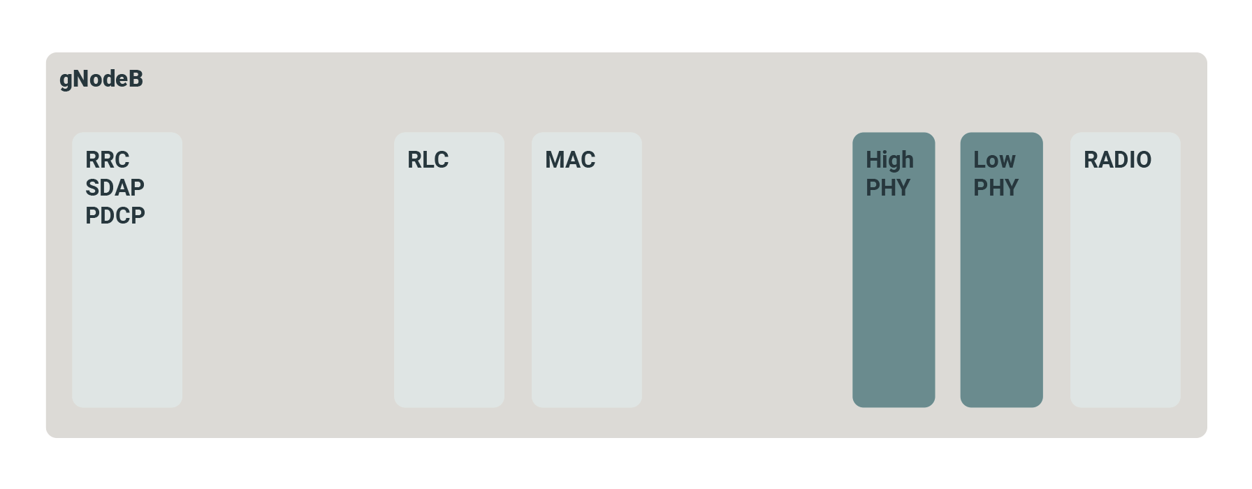
The gNodeB is a traditional integrated 5G NR with the RF, PHY and stack layers integrated into a single unit, with an NG interface to the 5GC Core Network.
Split 2 – 3GPP F1
The 3GPP defines this disaggregated RAN with separate (gNodeB-)CU and (gNodeB-)DU units with a high level split 2 using the 3GPP defined F1 interface. Split 2 is sometimes used in conjunction with a lower level splits 6, 7.2 and 8. This new 3GPP 5G RAN architecture introduces new terminology, interfaces and functional modules.
Split 6 – Small Cell Forum (SCF) nFAPI
The split 6 interface protocol is the Network FAPI (nFAPI), specified by the Small Cell Forum, where the MAC and PHY functions are physically separate.
Split 7.2 – O-RAN Open Fronthaul
A split 7 interface has been specified by the O-RAN Alliance, which has adopted the eCPRI interface as its basis. Whereas CPRI passes antenna samples using a proprietary protocol, eCPRI uses Ethernet.
Split 8
The split 8 interface is mainly being considered where there are legacy systems and existing hardware and cabling/fibre can be reused.
Industry Body Backed Split Option Definitions
3GPP specified the higher layer F1 interface, but additional interfaces at lower layer splits have also been specified by other industry bodies, and offer different relative advantages and disadvantages.
The Split 6 interface protocol is the Network FAPI (nFAPI), specified by the Small Cell Forum, where the MAC and PHY functions are physically separate.
The Split 7 interface has been specified by the O-RAN Alliance, which has adopted the eCPRI interface as its basis. Whereas CPRI passes digitised RF signals to the antenna using a proprietary serial protocol, eCPRI uses Ethernet. Moreover, in O-RAN fronthaul, it is frequency domain samples that are transported between the upper PHY and lower PHY, which leads to advantages.
The Split 8 interface is mainly being considered where there are legacy systems and existing hardware and cabling/fibre can be reused.
5G with Dynamic Spectrum Sharing (DSS) is a game-changer
Wireless Service Providers can tap spectrum currently used for 4G to launch nationwide 5G coverage with a simple network software upgrade, and deploy a “5G Ready” network to operate on 4G today, with easy upgrade to 5G without disruption.
What is Dynamic Spectrum Sharing (DSS)?
Dynamic Spectrum Sharing (DSS) is emerging as a key part of mobile service providers’ 5G strategy. Using cellular base stations with DSS offers the lowest total cost of ownership (TCO) to launch 5G in bands currently used for 4G – enabling nationwide 5G coverage in short time after launch. Dynamic Spectrum Sharing allows an existing LTE carrier to operate 5G New Radio (NR) and LTE simultaneously – with a simple software upgrade. The solution is based on innovative intelligent scheduler algorithms that enable optimal performance as the mix of 4G and 5G devices in the network changes over time.
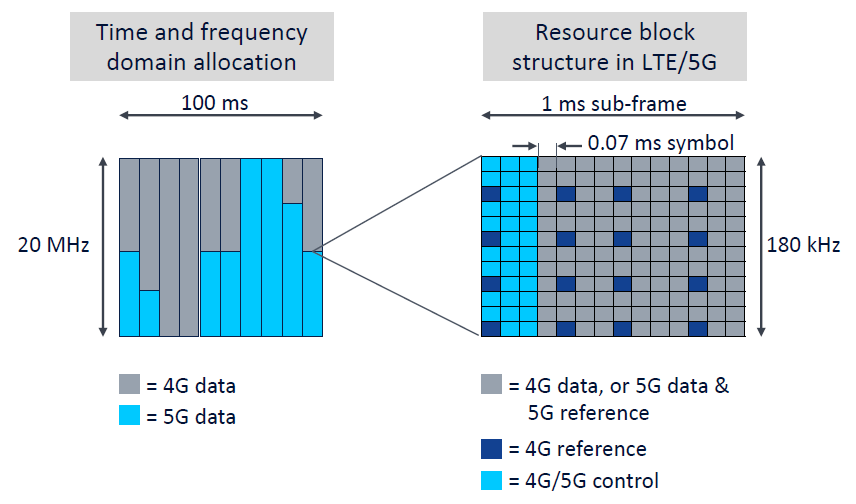
From the early stages of research into 5G NR, when developers began to map 5G transmissions to time-frequency resources, the developers created the possibility for holes in the 5G transmission grid which could be used for 4G LTE transmissions. This means that, by simultaneously sharing frequency bands which are already available today, service providers can fire up 5G on existing LTE bands without actually shutting off LTE. This means that, as well as having the option to roll out 5G on existing DSS-compatible 4G hardware, operators can keep the LTE network up and running while starting 5G. This can make it far easier for operators to transition to 5G in the coming years.
How does DSS work?
The 5G physical layer is designed to be so similar to 4G in 3GPP that DSS becomes feasible with the same subcarrier spacing and similar time domain structure. DSS is designed to be backwards compatible with all existing LTE devices. communication service providers (CSPs) therefore need to maintain LTE cell reference signal (CRS) transmission. 5G transmission is designed around LTE CRS in an approach called CRS rate matching.
Picture credit – Nokia
DSS with 5G carrier aggregation (CA) releases the full potential of the technology, especially when combined with standalone (SA) architecture. CA provides the highest data rates while SA maximizes low-band coverage and access to 5G services. DSS will be supported by a growing number of 5G devices from 2020 onwards, with widespread support for devices with DSS, SA and CA available during the course of 2021. The introduction of DSS capability therefore aligns with the growing availability of devices
Diagram credit – Nokia
One option is for DSS to use a single shared baseband card for 4G and for 5G, which obviously precludes a multi-vendor solution for 4G and 5G. The other option is to keep the existing 4G baseband and add a new 5G baseband. The scheduling between the two baseband functions is then based on a fast Xp interface between 4G and 5G. This interface is not open and works only for a single vendor, so CSPs must use the same vendor in 4G and 5G if they use DSS
Diagram credit – Nokia
Conclusions
DSS is a great solution for flexibly refarming spectrum to 5G. Operators can build a “5G ready” network today, operating in 4G, and switch over partially – or fully – to 5G at any later date, without losing back-compatibility for 4G device users
Exploring the 5G NR Frame Structure used in 5G New Radio networks and 5G Radio equipment: including gNodeB and 5G CPE devices
Frame Structure
The 5G NR frame structure is defined by the 3GPP and here we present details of the NR Frame Structure that is specified in 3GPP specification (38.211).
Numerology – Subcarrier Spacing
Compared to LTE numerology (subcarrier spacing and symbol length), the most outstanding difference you can notice is that NR support multiple different types of subcarrier spacing (in LTE there is only one type of subcarrier spacing, 15 KHz). The types NR numerology is summarized in 38.211 and I converted the table into illustration to give you intuitive understanding of these numerology.
As you see here, each numerology is labeled as a parameter(u, mu in Greek). The numerology (u = 0) represents 15 kHz which is same as LTE. And as you see in the second column the subcarrier spacing of other u is derived from (u=0) by scaling up in the power of 2.
Numerology and Slot Length
As illustrated below, Slot length gets different depending on numerology. The general tendency is that slot length gets shorter as subcarrier spacing gets wider. Actually this tendency comes from the nature of OFDM. You would see further details on how the slot length is derived in Radio Frame Structure section.
Numerology and Supported Channels
Not every numerology can be used for every physical channel and signals. That is, there is a specific numerologies that are used only for a certain type of physical channels even though majority of the numerologies can be used any type of physical channels. Following table shows which numerologies can be used for which physical channels.
< 38.300-Table 5.1-1: Supported transmission numerologies and additional info.>
OFDM Symbol Duration
Parameter / Numerlogy (u)
0
1
2
3
4
Subcarrier Spacing (Khz)
15
30
60
120
240
OFDM Symbol Duration (us)
66.67
33.33
16.67
8.33
4.17
Cyclic Prefix Duration (us)
4.69
2.34
1.17
0.57
0.29
OFDM Symbol including CP (us)
71.35
35.68
17.84
8.92
4.46
Numerology – Sampling Time
Sampling time can be defined differently depending on Numerogy (i.e, Subcarrier Spacing) and in most case two types of Timing Unit Tc and Ts are used.
Tc = 0.509 ns
Ts = 32.552 ns
See Physical Layer Timing Unit page to see how these numbers are derived and to see some other timing units.
Radio Frame Structure
As described above, in 5G/NR multiple numerologies(waveform configuration like subframe spacing) are supported and the radio frame structure gets a little bit different depending on the type of the numerology. However, regardless of numerology the length of one radio frame and the length of one subfame is same. The length of a Radio Frame is always 10 ms and the length of a subframe is always 1 ms.
What changes to accommodate the physical property of the different numerology ? Answer is to put different number of slots within one subfame. There is another varying parameter with numerology. It is the number of symbols within a slot. However, the number of symbols within a slot does not change with the numerology, it only changes with slot configuration type. For slot configuration 0, the number of symbols for a slot is always 14 and for slot configuration 1, the number of symbols for a slot is always 7.
Now look at details of radio frame structure for each numerology and slot configuration:
< Normal CP, Numerology = 0 >
In this configuration, a subframe has only one slot in it, it means a radio frame contains 10 slots in it. The number of OFDM symbols within a slot is 14.
< Normal CP, Numerology = 1 >
In this configuration, a subframe has 2 slots in it, it means a radio frame contains 20 slots in it. The number of OFDM symbols within a slot is 14.
< Normal CP, Numerology = 2 >
In this configuration, a subframe has 4 slots in it, it means a radio frame contains 40 slots in it. The number of OFDM symbols within a slot is 14.
< Normal CP, Numerology = 3 >
In this configuration, a subframe has 8 slots in it, it means a radio frame contains 80 slots in it. The number of OFDM symbols within a slot is 14.
< Normal CP, Numerology = 4 >
In this configuration, a subframe has 16 slots in it, it means a radio frame contains 160 slots in it. The number of OFDM symbols within a slot is 14.
< Extended CP, Numerology = 2 >
In this configuration, a subframe has 8 slots in it, it means a radio frame contains 80 slots in it. The number of OFDM symbols within a slot is 12.
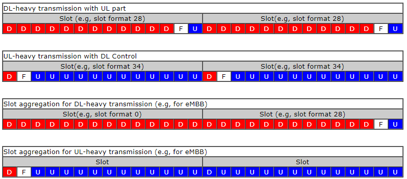
Slot Format
Slot Format indicates how each of symbols within a single slot is used. It defines which symbols are used for uplink and which symbols are used for downlink within a specific slot. In LTE TDD, if a subframe (equivalent to a Slot in NR) is configured for DL or UL, all of the symbols within the subframe should be used as DL or UL. But in NR, the symbols within a slot can be configured in various ways as follows.
We don’t need to use every symbols within a slot (this can be a similar concept in LAA subframe where only a part of subframes can be used for data transmission).
Single slot can be divided into multiple segments of consecutive symbols that can be used for DL , UL or Flexible.
Theoretically we can think of almost infinite number of possible combinations of DL symbol, UL symbol, Flexible Symbol within a slot, but 3GPP allows only 61 predefined symbol combination within a slot as in following table. These predefined symbol allocation of a slot called Slot Format. (For the details on how these Slot Format is being used in real operation, refer to Slot Format Combination page).
<38.213 v15.7 -Table 11.1.1-1: Slot formats for normal cyclic prefix>
D : Downlink, U : Uplink, F : Flexible
Symbol Number in a slot
Format
0
1
2
3
4
5
6
7
8
9
10
11
12
13
0
D
D
D
D
D
D
D
D
D
D
D
D
D
D
1
U
U
U
U
U
U
U
U
U
U
U
U
U
U
2
F
F
F
F
F
F
F
F
F
F
F
F
F
F
3
D
D
D
D
D
D
D
D
D
D
D
D
D
F
4
D
D
D
D
D
D
D
D
D
D
D
D
F
F
5
D
D
D
D
D
D
D
D
D
D
D
F
F
F
6
D
D
D
D
D
D
D
D
D
D
F
F
F
F
7
D
D
D
D
D
D
D
D
D
F
F
F
F
F
8
F
F
F
F
F
F
F
F
F
F
F
F
F
U
9
F
F
F
F
F
F
F
F
F
F
F
F
U
U
10
F
U
U
U
U
U
U
U
U
U
U
U
U
U
11
F
F
U
U
U
U
U
U
U
U
U
U
U
U
12
F
F
F
U
U
U
U
U
U
U
U
U
U
U
13
F
F
F
F
U
U
U
U
U
U
U
U
U
U
14
F
F
F
F
F
U
U
U
U
U
U
U
U
U
15
F
F
F
F
F
F
U
U
U
U
U
U
U
U
16
D
F
F
F
F
F
F
F
F
F
F
F
F
F
17
D
D
F
F
F
F
F
F
F
F
F
F
F
F
18
D
D
D
F
F
F
F
F
F
F
F
F
F
F
19
D
F
F
F
F
F
F
F
F
F
F
F
F
U
20
D
D
F
F
F
F
F
F
F
F
F
F
F
U
21
D
D
D
F
F
F
F
F
F
F
F
F
F
U
22
D
F
F
F
F
F
F
F
F
F
F
F
U
U
23
D
D
F
F
F
F
F
F
F
F
F
F
U
U
24
D
D
D
F
F
F
F
F
F
F
F
F
U
U
25
D
F
F
F
F
F
F
F
F
F
F
U
U
U
26
D
D
F
F
F
F
F
F
F
F
F
U
U
U
27
D
D
D
F
F
F
F
F
F
F
F
U
U
U
28
D
D
D
D
D
D
D
D
D
D
D
D
F
U
29
D
D
D
D
D
D
D
D
D
D
D
F
F
U
30
D
D
D
D
D
D
D
D
D
D
F
F
F
U
31
D
D
D
D
D
D
D
D
D
D
D
F
U
U
32
D
D
D
D
D
D
D
D
D
D
F
F
U
U
33
D
D
D
D
D
D
D
D
D
F
F
F
U
U
34
D
F
U
U
U
U
U
U
U
U
U
U
U
U
35
D
D
F
U
U
U
U
U
U
U
U
U
U
U
36
D
D
D
F
U
U
U
U
U
U
U
U
U
U
37
D
F
F
U
U
U
U
U
U
U
U
U
U
U
38
D
D
F
F
U
U
U
U
U
U
U
U
U
U
39
D
D
D
F
F
U
U
U
U
U
U
U
U
U
40
D
F
F
F
U
U
U
U
U
U
U
U
U
U
41
D
D
F
F
F
U
U
U
U
U
U
U
U
U
42
D
D
D
F
F
F
U
U
U
U
U
U
U
U
43
D
D
D
D
D
D
D
D
D
F
F
F
F
U
44
D
D
D
D
D
D
F
F
F
F
F
F
U
U
45
D
D
D
D
D
D
F
F
U
U
U
U
U
U
46
D
D
D
D
D
F
U
D
D
D
D
D
F
U
47
D
D
F
U
U
U
U
D
D
F
U
U
U
U
48
D
F
U
U
U
U
U
D
F
U
U
U
U
U
49
D
D
D
D
F
F
U
D
D
D
D
F
F
U
50
D
D
F
F
U
U
U
D
D
F
F
U
U
U
51
D
F
F
U
U
U
U
D
F
F
U
U
U
U
52
D
F
F
F
F
F
U
D
F
F
F
F
F
U
53
D
D
F
F
F
F
U
D
D
F
F
F
F
U
54
F
F
F
F
F
F
f
D
D
D
D
D
D
D
55
D
D
F
F
F
U
U
U
D
D
D
D
D
D
62-254
Reserved
255
UE determines the slot format for the slot based on tdd-UL-DL-ConfigurationCommon, or tdd-ULDL-ConfigurationDedicated and, if any, on detected DCI formats
Why we need so many different types of slot formats ? Key goal is to make NR scheduling flexible especially for TDD operation. By applying a slot format or combining different slot formats in sequence, we can implement various different types of scheduling as in the following example:
TDD DL/UL Common Configuration
See TDD DL/UL Common Configuration page.
Resource Grid
The resource grid for NR is defined as follows. If you just take a look at the picture, you would think it is almost identical to LTE resource grid. But the physical dimension (i.e, subcarrier spacing, number of OFDM symbols within a radio frame) varies in NR depending on numerology.
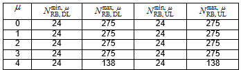
The maximum and minimum number of Resource blocks for downlink and uplink is defined as below (this is different from LTE)
< 38.211 v1.0.0 Table 4.4.2-1: Minimum and maximum number of resource blocks.>
Following is the table that I converted the downlink portions of Table 4.4.2-1 into frequency Bandwidth just to give you the idea on what is the maximum RF bandwidth that a UE / gNB need to support for single carrier.
u
min RB
Max RB
sub carrier spacing(kHz)
Freq BW min(MHz)
Freq BW max(MHz)
0
24
275
15
4.32
49.5
1
24
275
30
8.64
99
2
24
275
60
17.28
198
3
24
275
120
34.56
396
4
24
138
240
69.12
397.44
SS/PBCH
SS(PSS and SSS) and PBCH in NR is transmitted in the same 4 symbol block as specified in the following table.
< Frequency Domain Resource Allocation >
Overall description on the resource allocation for SS/PBCH block is described in 38.211 – 7.4.3.1 Time-frequency structure of an SS/PBCH block and followings are the summary of the specification.
SS/PBCH block consists of 240 contiguous subcarriers (20 RBs)
The subcarriers are numbered in increasing order from 0 to 239 within the SS/PBCH block
The UE may assume that the contents(value) of the resource elements denoted as ‘Set to 0’ in Table 7.4.3.1-1 are set to zero. (This mean that the contents of the gray colored resource element in the SSB diagram shown below is filled with zeros).
k_ssb corresponds to the gap between Subcarrier 0 of SS/PBCH block and Common Resource Block
is obtained from the higher-layer parameter OffsetToPointA
offset-ref-low-scs-ref-PRB corresponds to the FrequencyInfoDL.absoluteFrequencyPointA. Data type is ARFCN-ValueNR and the range of the value is INTEGER (0..3279165) in integer.
There are two types of SS/PBCH Block
Type A (Sub 6)
k_ssb(k0 in older spec) = {0,1,2,…,23}
4 LSB bits of k_ssb value can informed to UE via ssb-subcarrierOffset in MIB
The MSB bit is informed to UE via a bit within the PBCH Data ()
is expressed in terms of 15 Khz subcarrier spacing
u (numerology) = {0,1}, FR1 (sub 6 Ghz)
is expressed in terms of 15 Khz subcarrier spacing
Type B (mmWave)
k_ssb(k0 in older spec) = {0,1,2,…,11}
the whole k_ssb value can be informed to UE via ssb-subcarrierOffset in MIB
is expressed in terms of the subcarrier spacing provided by the higher-layer parameter subCarrierSpacingCommon in MIB .
u (numerology) = {3,4}, FR2 (mmWave)
is expressed in terms of 60 Khz subcarrier spacing
NOTE : Actually understanding k_ssb and in the resource grid often get confusing and hard to visualize. The following is an example where the SubcarrierSpacingCommon is equal to 30KHz, and k_ssb=2, where in such a case the center of the first subcarrier of the SS/PBCH Block (which has 15KHz SCS) coincides with the center frequency of the subcarrier 1 of
This table can be represented in Resource Grid as shown below. Note that the position of PBCH DM-RS varies with v and the value v changes depending on Physical Cell ID.
< Time Domain Resource Allocation >
Following table indicates the first OFDM symbol number (s) where SS/PBCH is transmitted. This is based on 38.213 – 4.1 Cell Search.
The document states as follows :
For a half frame with SS/PBCH blocks, the number and first symbol indexes for candidate SS/PBCH blocks are determined according to the subcarrier spacing of SS/PBCH blocks as follows.
This means that [38.213 – 4.1 Cell Search] specifies SS/PBCH location in time domain as illustrated below.
< Start Symbols for each subcarrier spacing and frequency >
Followings are examples of SSB Transmission for each cases. For the simplicity, I set the frequency domain location of SSB block to be located at the bottom of the system bandwidth, but in reality the frequency domain location can change to other location (e.g, center frequency of the system bandwidth). The main purpose of these examples is o show the time domain location (transmission pattern) of each cases. In real deployment, it is highly likely (but not necessarily) that the frequency domain location of the SSB located around the center frequency.
The example below shows how you can correlate the above table to the SSB transmission plot shown in the following examples.
For Further Information
For more information about 5G NR Frame structure used in 5G Radios:
Do the new security and privacy features of 5G require a new SIM card? Simple answer is no. However, the complete answer is more complex.
SIM cards are Smart Cards with data
In this article, we refer to these newer smart cards as Rel 99+ USIM which are compatible with 3GPP Release 1999 (first 3G specifications) and afterwards. These Rel 99+ USIMs can be used to access every generation of mobile networks, including 5G. Such backward and forward compatibility is achieved by the carefully-designed offloading of some computations and storage to mobile phones.
5G Networks: Logo (C) 3GPP
While accessing the 5G system is one thing, the question we have is whether using the “new” security and privacy features of 5G requires a new kind of USIM other than Rel 99+ USIMs which could be used for 4G security. This is a valid question and something which we address below. For the sake of brevity, in this post, we do not touch upon other new features in 5G that do not concern USIM.
SIM Identity and access management (IdaM)
In 5G, subscription permanent identifier (SUPI) could be in two formats, one is the legacy format called international mobile subscriber identity (IMSI) and another is the format newly adopted in 5G called network access identifier (NAI). Furthermore, 5G provides at least two methods of authentication and key agreement (AKA) for accessing the network. One such method, 5G AKA, is an evolution of the authentication method in 4G. Another, called EAP-AKA’, is a method now widely adopted in 5G for broader use of the Extensible Authentication Protocol (EAP) framework.
In any case, from the IdaM viewpoint, the Rel 99+ USIMs that could be used in 4G are still compatible with 5G, in that they can be used to authenticate and gain access to the 5G system. The main reason for this forward compatibility is the fact that there is no need for a new permanent security key shared between USIMs and the network. Another reason is that newer storage and computations required for new security features can be offloaded to mobile phones, like the calculation of a new type of AKA response and new session keys.
The adoption of the EAP framework in 5G means that it is possible for other methods than EAP-AKA’, such as Extensible Authentication Protocol-Transport Layer Security (EAP-TLS), to be used for isolated deployments. In those cases, it could be such that the USIM’s role is skipped. It is also worth noting that, just as with 4G networks, any smart cards older than Rel 99+ USIM (which may be called Rel 98- SIM) cannot be used to access 5G.
5G SIM Privacy
5G has introduced significant privacy enhancements in terms of how permanent and temporary identifiers are used.
An important topic which is use of subscription concealed identifier (SUCI). The SUCI, which basically hides the SUPI over-the-air, can be calculated using standardized schemes like so-called Profile A and Profile B. It also requires some new parameters like public key of the home network, scheme identifier, and routing indicator. While SUCI calculations using Profile A/B can be offloaded to mobile phones, the standards only permit the storage of the new parameters in the USIM. For brevity, in this post we will not discuss the proprietary option where SUCI calculation can be done in USIMs using non-standardized schemes.
Therefore, Rel 99+ USIMs can be used to store the parameters required for SUCI calculation with Profile A/B given that they support creating the necessary files (DF5GS/EFSUCI_Calc_Info/EFRouting_Indicator). This is also true for Rel 99+ USIMs already in the field i.e. if they support some mechanisms like remote file management over-the-air (OTA), then they could be used for storing the parameters required for SUCI calculation with Profile A/B. Otherwise, SUCI will be calculated by mobile phones using the so-called “null-scheme” which is a dummy scheme and does not hide SUPI. In other words, Rel 99+ USIMs that cannot store new parameters required for SUCI calculation could still be used to get access to the 5G system but without the ability to hide the SUPI over-the-air.
Note that there are also other privacy enhancements in 5G like the strict refreshment of temporary identifiers, decoupling of permanent identifiers from paging procedures, and partial confidentiality protection of initial messages. For these features, the USIM’s role is not required in the standards.
Steering of roaming (SoR) and UE parameter update (UPU)
SoR and UPU are two new procedures in 5G between mobile phones and the home network. These new procedures enable the home network to update configuration parameters in mobile phones and/or USIM using control plane signaling. It means that, in 5G, the home network has an alternative to existing mechanisms like over-the-air (OTA) updates that use SMS as transport.
As well as handling of the so-called “secured packet” that mobile phones can basically relay to the USIM, the scope of SoR and UPU procedures include parameters like operator controlled PLMN selector with access technology, default configured network slice selection assistance information (NSSAI), and routing indicator.
Handling of new control plane signaling including security, like calculation and verification of new security tokens, are offloaded to mobile phones. Furthermore, in some cases, storage of parameters is also offloaded to mobile phones like default configured NSSAI and mobile phone’s copy of operator controlled PLMN selector with access technology. Therefore, in such cases, special support from the USIM is not required for SoR and UPU in 5G, which means that Rel 99+ USIMs can be used.
There are other cases when the storage of the new/updated parameters is still done in USIM, like routing indicator (EFRouting_Indicator), USIM’s copy of operator controlled PLMN selector with access technology (EFOPLMNwACT), and any file handling done by the “secured packet”. Even then, Rel 99+ USIMs are still compatible with SoR and UPU in 5G given that they support the necessary file management operations.
5G SIM card Summary
To summarize, impacts on USIMs by relevant security and privacy features that are new in 5G.
from IdaM viewpoint, Rel 99+ USIMs which could be used for 4G are still compatible to get access in 5G.
Regarding SUPI privacy, Rel 99+ USIMs can be used to enable SUCI calculation with Profile A/B as long as they support necessary file management operations. Regarding other privacy features, Rel 99+ USIMs are fully compatible in their current form.
From a perspective of SoR/UPU procedures, Rel 99+ USIMs are compatible in their current form only in some cases, while in other cases compatibility will depend on them supporting necessary file management operations.
Whether/how to use the above mentioned new security and privacy features is in the remit of the network operator and therefore, even in worst case, they will not prohibit access to the plethora of other basic 5G features.
Technical notes
IdaM part – The formats of SUPI (IMSI and NAI) are defined in 3GPP TS 23.003, see clauses 2.2A, 2.2, and 28.7.2. The new type of AKA response is called RES* and new session keys are called KAUSF and KSEAF. See clauses 6.1 in 3GPP TS 33.501 for details. In Annex B of that TS, you will also find details of using EAP-TLS
Privacy part – The formats of SUCI are defined in clauses 2.2B and 28.7.3 in 3GPP TS 23.003. Clause 6.12 and Annex C in 3GPP TS 33.501 contain main details of subscription identifier privacy. Clause 4.4.11 in 3GPP TS 31.102 specifies USIM files specific to 5G
SoR/UPU part – The new security tokens are called SoR-MAC-IAUSF, UPU-MAC-IAUSF, SoR-MAC-IUE, and UPU-MAC-IUE. See the main details of SoR and UPU can be found in clauses 6.14 and 6.15 in 3GPP TS 33.501, Annex C in TS 23.112, and Clause 4.20 in TS 23.502
Beamforming, Beam Steering & Beam Switching with Massive MIMO for 5G compared
Combining the high propagation loss of the millimeter wavelengths (mmWaves) employed in 5G new radio (5G NR) systems, plus the higher bandwidth demands of users, combinations of beamforming techniques and massive Multiple Input and Multiple Output (MIMO) are essential for increasing spectral efficiencies and providing cost-effective, reliable wireless network coverage.
Beamforming
Beamforming is the application of multiple radiating elements transmitting the same signal at an identical wavelength and phase, which combine to create a single antenna with a longer, more targeted stream which is formed by reinforcing the waves in a specific direction. The general concept was first employed in 1906 for trans-oceanic radio communications.
With more radiating elements that make up the antenna, the narrower the beam. An artifact of beamforming is side lobes. These are essentially unwanted radiation of the signal that forms the main lobe in different directions. Poor engineering of antenna arrays would result in excessive interference by a beamformed signal’s side lobe. The more radiating elements that make up the antenna, the more focused the main beam is and the weaker the side lobes are.
Figure 1: Beamforming with two and four radiating elements
While digital beamforming at the baseband processor is most commonly used today, analog beamforming in the RF domain can provide antenna gains that mitigate the lossy nature of 5G millimeter waves.
Beam steering and beam switching
Beam steering is achieved by changing the phase of the input signal on all radiating elements. Phase shifting allows the signal to be targeted at a specific receiver. An antenna can employ radiating elements with a common frequency to steer a single beam in a specific direction. Different frequency beams can also be steered in different directions to serve different users. The direction a signal is sent in is calculated dynamically by the base station as the endpoint moves, effectively tracking the user. If a beam cannot track a user, the endpoint may switch to a different beam.
Figure 2: Beam steering and beam switching
This granular degree of tracking is made possible by the fact that 5G base stations must be significantly closer to users than previous generations of mobile infrastructures.
Massive MIMO
Multiple input and multiple output (MIMO) antennas have long been a feature of commercial public wireless and Wi-Fi systems, but 5G demands the application of massive MIMO. To increase the resiliency (signal-to-noise ratio / SNR) of a transmitted signal and the channel capacity, without increasing spectrum usage, a common frequency can be steered simultaneously in multiple directions.
The successful operation of MIMO systems requires the implementation of powerful digital signal processors and an environment with lots of signal interference, or “spatial diversity”; that is a rich diversity of signal paths between the transmitter and the receiver.
Figure 3: Multiple input and multiple output (MIMO)
Diversity of arrival times, as the signal is bounced from different obstacles, forms multiple time-division duplexing (TDD) channels that can deliver path redundancy for duplicate signals or increase the channel capacity by transmitting different parts of the modulated data. First conceived of in the 1980s, there are a few differences between classic multi-user MU-MIMO and Massive MIMO, but fundamentally it is still the large number of antennas employed and the large number of users supported. The degree of MIMO is indicated by the number of transmitters and the number of receivers, i.e. 4×4.
Conclusion
Beamforming, Beam Steering, Beam Switching and Massive MIMO are key ingredients for 5G base stations.
We use technologies like cookies to store and/or access device information. We do this to improve browsing experience and to show personalized ads. Consenting to these technologies will allow us to process data such as browsing behavior or unique IDs on this site. Not consenting or withdrawing consent, may adversely affect certain features and functions.
Functional
Always active
The technical storage or access is strictly necessary for the legitimate purpose of enabling the use of a specific service explicitly requested by the subscriber or user, or for the sole purpose of carrying out the transmission of a communication over an electronic communications network.
Preferences
The technical storage or access is necessary for the legitimate purpose of storing preferences that are not requested by the subscriber or user.
Statistics
The technical storage or access that is used exclusively for statistical purposes.The technical storage or access that is used exclusively for anonymous statistical purposes. Without a subpoena, voluntary compliance on the part of your Internet Service Provider, or additional records from a third party, information stored or retrieved for this purpose alone cannot usually be used to identify you.
Marketing
The technical storage or access is required to create user profiles to send advertising, or to track the user on a website or across several websites for similar marketing purposes.