5G-NSA and 5G-SA networks compared

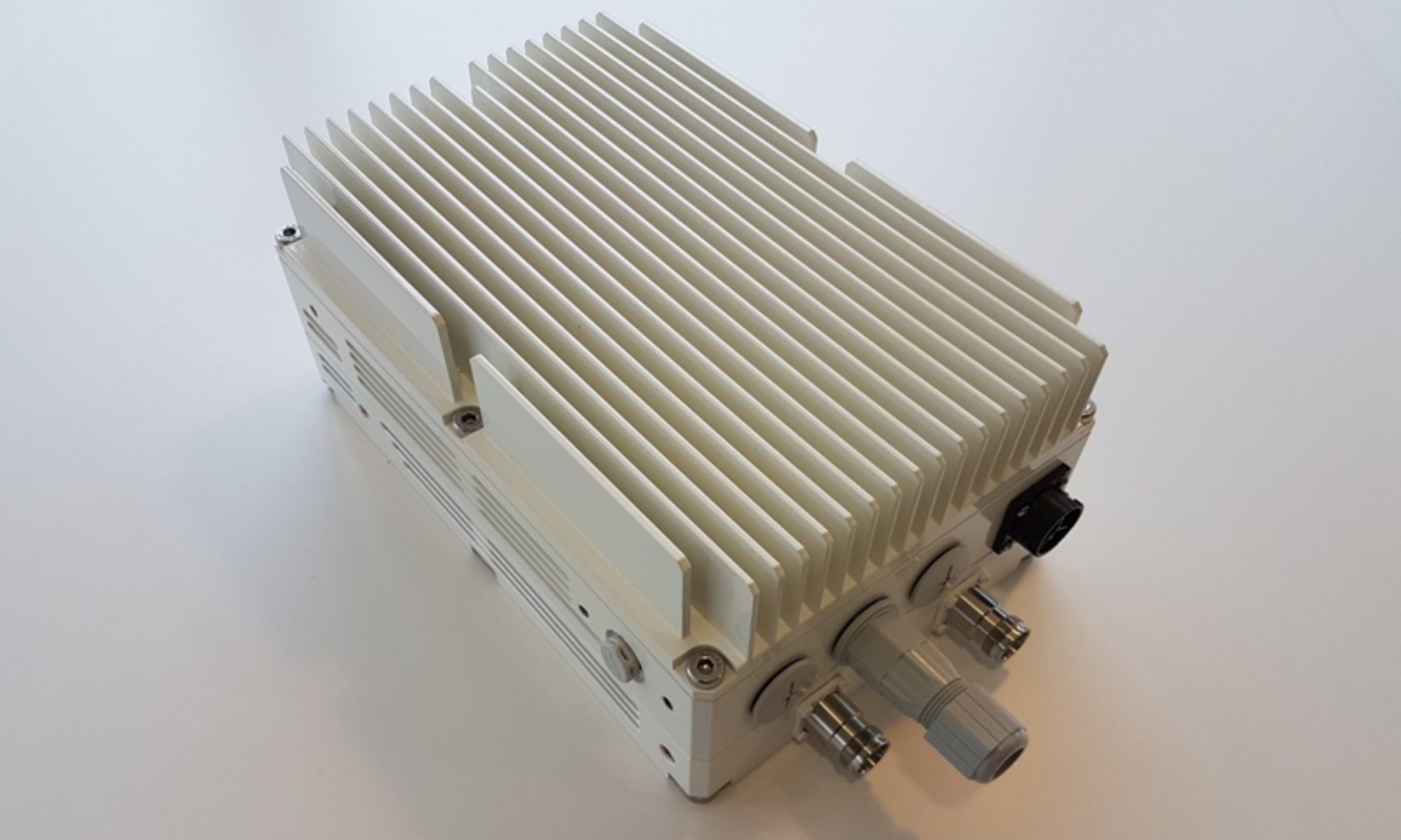
CableFree Remote Radio Head (RRH) used for 5G-SA and 5G-NSA networks

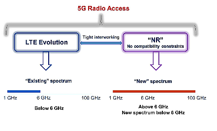
5G-NSA and 5G-SA network architecture compared

For leading mobile network operators (MNOs), 5G is mainly about offering high-speed connectivity to consumers, on devices that support fifth-gen (5G-NSA and 5G-SA) network services. To smoothly transition from the existing legacy core to 5G, MNOs have two pathways: Non-Standalone (NSA) or Standalone (SA) architecture. And while they are both means to the same end, NSA and SA are structurally and functionally different.

5G Networks:  5G-SA and 5G-NSA, SA, NSA architectures for modern mobile networks
5G Networks can be 5G-NSA or 5G-SA architecture

NSA allows operators to leverage their existing network investments in communications and mobile core instead of deploying a new core for 5G. 5G Radio Access Network (RAN) can be deployed and supported by the existing Evolved Packet Core (EPC), lowering CAPEX and OPEX. To further lower network operating costs, operators can adopt the virtualization of Control and User Plane Separation (CUPS) along with software-defined networking (SDN). These initial steps will help quickly unlock new 5G revenue streams and offer faster data speeds.

5G-SA is a completely new core architecture defined by 3GPP that introduces major changes such as a Service-Based Architecture (SBA) and functional separation of various network functions. Its architecture has the definite advantage of end-to-end high-speed and service assurance, particularly useful for MNOs who are set to commence new enterprise 5G services such as smart cities, smart factories, or other vertically integrated market solutions. The deployment model enables the rapid introduction of new services with quick time-to-market. However, it means additional investment and complexities of running multiple cores in the network.

Architecturally, NSA includes a new RAN, deployed alongside the 4G or LTE radio with the existing 4G Core or EPC. 5G SA, on the other hand, includes a new radio along with the 5G Core (5GC), comprising completely virtualized cloud-native architecture (CNA) that introduces new ways to develop, deploy, and manage services. 5GC supports high-throughput for accelerated performance than the 5G network demands. Its virtualized service-based architecture (SBA) makes it possible to deploy all 5G software network functions using edge computing.

5G-SA and 5G-NSA compared

5G Standalone (SA) vs 5G Non-Standalone (NSA)

5G-SA Architecture

According to a survey, 37% of MNOs will deploy 5G SA within two years; 27% of operators plan to deploy 5G SA within 12 to 18 months with an additional 10% increase within 24 months. 5G SA architecture will allow operators to address the fifth generation of mobile communications, including enhanced mobile broadband, massive machine-to-machine communications, massive IoT, and ultra-low latency communications.

CableFree Remote Radio Head (RRH) used for 5G-SA and 5G-NSA networks

Standalone 5G-NR comprises a new end-to-end architecture that uses mm-Waves and sub-GHz frequencies and this mode will not make use of the existing 4G LTE infrastructure. The SA 5G NR will use enhanced mobile broadband (eMBB), Ultra-Reliable and Low Latency Communications (URLLC), and huge machine-type communications (mMTC) to implement multi-gigabit data rates with improved efficiency and lower costs.

5G SA also enables more advanced network slicing capabilities, helping operators rapidly transition to both 5G New Radio (NR) and 5G as the core network. Network slicing, URLLC, and mMTC bring ultra-low latency along with a wide range of next-gen use cases like remote control of critical infrastructure, self-driving vehicles, advanced healthcare, and more. However, the NR advanced cases are not backward compatible with the EPC, which is the framework that provides converged voice and data on a 4G LTE network. The level of reliability and latency that 5G provides will be indispensable for handling smart-grid control machines, industrial automation, robotics, and drone control and coordination.

5G-NSA Architecture

NSA-5G NR is considered as the early version of SA 5G NR mode, in which 5G networks are supported by existing LTE infrastructure. It fundamentally concentrates on eMBB, where 5G-supported handsets and devices will make use of mmWave frequencies for increased data capacity but will continue to use existing 4G infrastructure for voice communications.

NSA helps MNOs launch 5G quickly for eMBB to get a competitive edge in the telecom market. NSA also helps leverage its existing LTE/VoLTE footprint to maximize the LTE installed base and boost capacity while increasing delivery efficiency. It will not support network slicing, URLLC, and mMTC, but its higher broadband speeds will enable services such as video streaming, augmented reality (AR), virtual reality (VR), and an immersive media experience.

Non-Standalone 5G NR will provide increased data-bandwidth by using the following two new radio frequency ranges:

  • Frequency range 1 (450 MHz to 6000 MHz) – overlaps with 4G LTE frequencies and is termed as sub-6 GHz. The bands are numbered from 1 to 255.
  • Frequency range 2 (24 GHz to 52 GHz) – is the main mmWave frequency band. The bands are numbered from 257 to 511.

Technical Differences between 5G SA and 5G NSA

The main difference between NSA and SA is that NSA provides control signaling of 5G to the 4G base station, whereas in SA the 5G base station is directly connected to the 5G core network and the control signaling does not depend on the 4G network. In simple terms, NSA is like adding a solid-state drive to an old computer, which can improve the system’s performance, while SA is like replacing it with a new computer that has newer technologies and optimum performance.

Some benefits include:

  • 5G-NSA is a low-cost update of core compared to a 5G Core needed for 5G-SA.
  • 5G-NSA eases 5G network deployments as it reuses existing 4G facilities, thus allowing rapid time to market for 5G mobile broadband.
  • With NSA, the deployment is faster and time-to-market is lower, as 4G locations can be used to install 5G radio. SA requires building 5G base stations and the back-end 5G core network to fully realize the characteristics and functions of 5G.
  • SA involves a 5G core with SBA for scalability and flexibility to deliver a superfast network with ultra-low latency for advanced 5G use cases.

5G Usage Scenarios in NSA and SA Operation

The requirements of 5G NR for the SA provide a complete set of specifications for the 5G core network that goes beyond NSA. The three major usage scenarios defined for 5G by the 3GPP and GSMA include:

  1. Enhanced mobile broadband (eMBB)
  2. Ultra-reliable and low latency communications (URLLC)
  3. Massive machine-type communications (mMTC)

Future 5G Networks Include both NSA and SA

Early adopters of 5G primarily focus on 5G-NSA deployments as they compete to deliver 5G speeds with a quick time to market. These MNOs can move to SA-based architecture over a period of time, which most plan to do. 5G-NSA deployment remains a mainstream solution given its ability to handle both 4G- and 5G-based traffic, keeping these early adopters ahead of their competition as they undertake their network transformation. 5G devices are not widespread so the need for 5G-SA-based architecture is still nascent.

For the future, the convergence of NSA and SA will help operators move to a full 5G network. A complete virtualized 5G architecture will allow MNOs to migrate and choose varied functionalities of their existing NSA solution to the 5GC platform, as new 5G services are launched, allowing them to monetize their investment gradually rather than move all at once and enabling them to recover their costs over time.

Although 5G-SA is a more mature network architecture compared to 5G-NSA, NSA will continue to be the more commonly chosen path to 5G. All NSA single-mode 5G phones launched this year or early next year will be valid for a decade, and as SA architecture permeates, more and more 5G-SA devices will be in our homes and businesses.

For Further Information

Please Contact Us

RadioMobile for 5G Network Planning

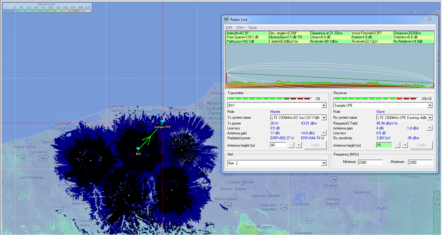
CableFree RadioMobile 5G LTE Coverage Planning example

RadioMobile: Popular software for 5G Network Coverage planning

RadioMobile is a widely-available software package which can be used for 5G Network Coverage planning, including path profiling and clearance criteria, power budgets, choosing antenna sizes and tower heights.

CableFree RadioMobile 5G LTE Coverage Planning example

For website for RadioMobile, please see this link here:

RadioMobile functions

For 5G Coverage Planning, the software package can be configured with the characteristics of your required radio network.

  • Transmit Power
  • Frequency Band
  • Antenna Gain
  • Receiver Sensitivity
  • Antenna heights
  • System losses
  • CPE types and locations

CableFree RadioMobile 5G LTE Coverage Planning example

Link Budget & Fade Margins

The software enables quick and rapid calculation of link budget and fade margins for any frequency band.

Terrain Database

The software uses the freely available SRTM terrain data which can download “on demand” for calculation of terrain heights.  Combined with LandCover, this enables estimation of trees/forests also.

Line of Sight

The software uses the terrain database to allows quick establishment of available Line of Sight and “what if” adjustment of antenna/tower heights in a 5G radio network design

Radio Fresnel Zone

RadioMobile automatically calculates the Fresnel Zone for any required link, with graphical display enabling quick feasibility and identification of any obstacles to be noted.

Radio Parameters & Network Properties

Any new user to Radio Mobile will have to enter link parameters for the chosen equipment.  This includes transmit power, receive sensitivity and antenna gains.  Some vendors such as CableFree include this data as a planning service with their products

CableFree RadioMobile 5G LTE Coverage Planning example

Radio Mobile: Free to Use

The Radio Mobile software is free to use including for commercial use.  Radio Mobile software is a copyright of Roger Coudé.  The author notes:

Although commercial use is not prohibited, the author cannot be held responsible for its usage. The outputs resulting from the program are under the entire responsibility of the user, and the user should conform to restrictions from external data sources.

For Further information

For More Information about Microwave Link Planning, we will be delighted to answer your questions. Please Contact Us

The Importance of Low-PIM for 5G LTE Networks

5G Technology: NSA & SA modes

In order to understand the importance of low-PIM antennas, cable and connectors in a modern 5G network, it is critical to understand what PIM refers to. PIM stands for Passive Intermodulation. It is a problem that happens largely in passive devices such as antennas, cables and connectors where interfering signals are generated by nonlinearities within a wireless system’s mechanism. Amplitude modulation or the mixing of two signals occurs, producing difference in signals within a specific band leaving behind significant interloping.

5G Networks Low PIM Passive Intermodulation
5G Networks

PIM: Nonlinearity Effects

Passive intermodulation product is also explained as resulting from the mixing of two high power natures at the nonlinearities of devices, such as in corroded connectors, metal oxide intersections and divergent metals. As the signal amplitude goes up, the nonlinearities effect will be very significant. Higher intermodulation result as lots of products on first inspection would show a system that is not just linear but seemingly incapable of producing intermodulation.

PIM Distortion & Telecommunication

A single internet provider such as a broadband carrier can also produce PIM in case it goes through a fault or a surface that generates PIM. Such distortions in telecommunication signals would look like side lobes interfering with end-to-end channels and hinder coverage.  In most communication systems today, PIM is a serious problem. Where there is a sharing of received highly powerful and transmitted signal, PIM interference is a serious vulnerability. After interference of PIM in the path of reception, filtering or unscrambling it is very difficult.

The Real Cause Of Passive Intermodulation

When mechanical components interact, particularly where two distinct metals connect, the result is nonlinear elements. A major cause is mostly unlike material’s junctions leading to Passive Intermodulation manifestation in coax cables, antennas and coax connectors among others. This is brought about by oxidation, loosely done connectors, corrosion, dirt, and rust among others, including any kind of adulteration on the passive devices. PIM is also caused by close metal objects from anchors, pipes, guy wires to roof flashings resulting in a nonlinearity that allows a mix. As the nonlinearity goes up, the PIM reception amplitude also surge.

Other PIM sources to avoid include a number of ferromagnetic materials such as a number of metals like steel, nickel and ferrites. Such elements display hysteresis once they come into contact with backing magnetic fields. Mechanical contacts done shoddily, cracked and cold solder joints, workmanship and manufacturing faults, among others, cause serious levels of PIM.

The Conditions That Bring About PIM

Normally, to bring about Passive Intermodulation, two fairly powerful RF signals rather close in terms of frequency are required. High power transmitters of about 20 watts and above will see the outputs creating PIM. As the power goes up, more severe the PIM effects produced.

Another important aspect to note about Passive Intermodulation is that as the components soar in age, PIM increases. An older system is very susceptible, including surroundings afflicted by high temperatures, lots of air pollution, extreme vibrations or salted air.

Other PIM Negative Effects

Apart from interfering with signals, Passive Intermodulation has other negative effects, especially on a receiver that usually has a high sensitivity. As interference of the signals takes place, the desired signals will be blocked as the noise floor goes up. Interference of the signals has also been deemed to lower the sensitivity of the receiver. In a typical cell signal setting anywhere, the negative end effects would be manifested in serious scenarios such as dropped calls, low system capacity among others.

Which Wireless Networks are Most Affected?

Most PIM problems are mostly susceptible to internet cell networks such as 4G & 5G LTE, HSPA and CDMA. For all of these, Passive Intermodulation is a significant challenge.

FDD-LTE has been cited as being highly sensitive to Passive Intermodulation effects. Where the PIM levels of interference are elevated, the performance and efficiency of LTE networks is greatly hampered. As this occurs, it is possible for the base station to mistake distorted signal as a channel in use thereby refusing to have the channel assigned. The result in the system is the loss of revenue, critical channel capacity and airtime.

Since modern equipment is largely sensitive in its nature, the lowest Passive Intermodulation effect levels are capable of brutally degrading the performance. For instance, a single one decibel loss in uplink sensitivity following PIM interference has been found to lower reception by over 10 percent.

DAS Implementations

PIM problems have been cited in lots of macro sites in external environments, an issue that had to be sorted out. In DAS (distributed antenna systems), the reliability and high data amount values are critical; lots of components appear in the path of the radio frequencies leading to PIM effects. These systems require passive components from directional to hybrid couplers, coax, and splitters among others to be placed near the source of the signal. As a result, passive components PIM specification has to be of the utmost level.

Modern Passive Components And PIM

Modern low-PIM passive components such as connector series are designed with installation ease in mind to provide the most desired mechanical and electrical reliability. They come in handy where low-Passive Intermodulation effect connection is required such as in installations in need of coax lengthy cable jumpers for the provision of low Passive Intermodulation levels and superb RF performance.

What Low-PIM Means to the Network Operator

To any consumer, integrator, or installer, high PIM levels mean the cellular reception will be very poor and the bandwidth will be limited. For a carrier, it means customers will not trust their cellular services and will probably move on to competing service provider. Low-PIM passive components mean that the signal will be strong offering extra and reliable bandwidth for customers and a perfect scenario for all involved. As a result, the modern low Passive Intermodulation antennas, cables and connectors among other passive components are designed for everyday use in a design perfectly harnessed to lower Passive Intermodulation. All these components arrive ready for use having been tested for seamless installation.

PIM Testing

Today users expect their cell phones to have a consistent signal no matter the mobile device they are using. All network operators work tirelessly to ensure the signal is highly improved. Cell phone signal boosters offering perfect signal amplifiers for use in residential and commercial setups where the signal is poor and unreliable, including every single passive component maker is alive to the PIM effect. Therefore PIM testing today is a highly critical process that will probably continue being so.

A typical 4G LTE network sees a high capacity 100 Mbps to 1Gbps data rate and increasing each year. Such a high rate of transmission keeps on exposing the susceptibility of networks to PIM interference on a large scale. The fidelity of a 4G LTE is hedged on network superiority than 2G or 3G networks.

The carrier, consumer, low-Passive Intermodulation components manufacturer, cell phone signal boosters and antennas manufacturers as well have to always consider Passive Intermodulation interference in their assembly processes. Passive Intermodulation testing and assuring peak low-PIM performance is thus imperative.

Low-PIM Connectors

Low-PIM connectors for instance are designed with contact connectors on the outside and center using a single construction piece as much as possible. N-type connectors among others are being over-molded in a way that eliminates thermal stresses, vibration and wind effects.

The design incorporates lots of aspects and forces of contact assuring sufficient pressure for the prevention of Passive Intermodulation, including gold or silver-plated mid contacts while the connector bodies are white bronze or silver plated. All passive components from connectors, cables to antennas are being manufactured in controlled environments by highly trained professionals who understand the desirability of low PIM.

Passive Intermodulation DAS Specifications

Low-PIM specification for DAS solutions is very important. To know how low you should aim for, you can stick to the vendors mostly aimed -110 dBc or -153 dBc for top of the range solutions. Note that the specification need to be constantly spread in all the bands from 4G LTE, 3G to 2G right from the 700 MHz frequency to as high as 2.7 GHz. This assures a consistent superb performance for every device and satisfaction for every customer.

Passive Intermodulation Effects During Installation

Even with the proper top quality low-PIM passive components and DAS solutions you can still suffer Passive Intermodulation effects. This can happen as you install or after installing the low-Passive Intermodulation passive device. If you have suspended ceiling grids or you rebar ceiling grids, you have metallic objects on the path of the cell signal, identify this with a view to minimizing Passive Intermodulation. At times, these metal objects are hard to avoid. Directional antennas can help mitigate their effects to a greater extent.

Seek to ensure connectors, cables and other low-Passive Intermodulation passive components installed are periodically inspected to avoid such effects as corrosion. As the component deteriorates without proper inspection Passive Intermodulation will be elevated.

The most important thing is to stick to low-PIM interior antennaslow-PIM RF Splitters, as well as cables, connectors, couplers and other passive components. Low-PIM solutions will eliminate the costly requirement of upgrading these components, ensuring your cell phone signal is never interrupted by high-PIM effects.

For Further Information

Please Contact Us
5G NR: New Radio

5G NR (New Radio) is a new radio access technology (RAT) developed by 3GPP for the 5G (fifth generation) mobile network. It was designed to be the global standard for the air interface of 5G networks.

The 3GPP specification 38 series provides the technical details behind NR, the RAT beyond LTE.

The study on NR within 3GPP started in 2015, and the first specification release was made available by the end of 2017. While the 3GPP standardization process was ongoing, industry had already begun efforts to implement infrastructure compliant with the draft standard, with the expectation that the first large scale commercial launch of 5G New Radio would occur in 2019.

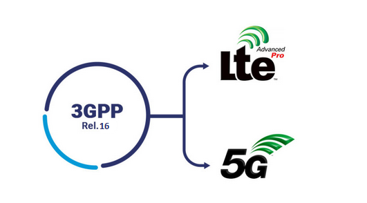
5G NR: 3GPP Release 16 includes 5G definitions
5G New Radio: 3GPP Release 16 includes 5G definitions

Frequency bands

The Frequency bands for 5G New Radio are being separated into two frequency ranges:[4]

Frequency Range 1 (FR1), including sub-6 GHz frequency bands
Frequency Range 2 (FR2), including frequency bands in the mmWave range (20-60GHz)

5G NR:  New Radio Interface

5G NR Development

In 2018, 3GPP published Release 15, which include what is described as “Phase 1” standardization for the 5G NR standard. 3GPP is expected to publish Release 16, which include the “Phase 2” of 5G NR, by the end of year 2019

5G NR Deployment modes

Initial launches will depend on existing LTE 4G infrastructure in non-standalone (NSA) mode, before maturation of the standalone (SA) mode with the 5G core network.

Non-Standalone mode

Non-Standalone (NSA) mode of 5G New Radio refers to an option of 5G NR deployment that depends on the control plane of existing LTE network for control functions, while 5G NR exclusively focused on user plane. The advantage of doing so is reported to speed up 5G adoption, however some operators and vendors have criticized prioritizing the introduction of 5G NR NSA on the grounds that it could hinder the implementation of the standalone mode of the network.

Standalone mode

Standalone (SA) mode of 5G New Radio refers to using 5G cells for both signalling and information transfer. It includes the new 5G Packet Core architecture instead of relying on the 4G Evolved Packet Core. It would allow the deployment of 5G without the LTE network. It is expected to have lower cost, better efficiency, and assist development of new use cases.

For Further Information

Please Contact Us
5G Frequency Bands

5G Networks

Frequency bands for 5G are divided into “sub 6GHz” and “mmWave” bands. “Sub 6” is generally for longer range coverage, with in-building penetration. “mmWave” bands use higher frequencies which offer short range, and no or little penetration of building structures.

This list of 5G frequency bands is taken from the latest published version of the 3GPP TS 38.101,the following tables list the specified frequency bands and the channel bandwidths of the 5G NR standard.

Note that the NR bands are defined with prefix of “n”. When the NR band is overlapping with the 4G LTE band, they share the same band number.

Frequency Range 1

BandDuplex mode[A 1]ƒ (MHz)Common nameSubset of bandUplink[A 2] (MHz)Downlink[A 3] (MHz)Duplex spacing (MHz)Channel bandwidths[5] (MHz)
n1FDD2100IMTn651920 – 19802110 – 21701905, 10, 15, 20
n2FDD1900PCS[A 4]n251850 – 19101930 – 1990805, 10, 15, 20
n3FDD1800DCS1710 – 17851805 – 1880955, 10, 15, 20, 25, 30
n5FDD850CLR824 – 849869 – 894455, 10, 15, 20
n7FDD2600IMT‑E2500 – 25702620 – 26901205, 10, 15, 20
n8FDD900Extended GSM880 – 915925 – 960455, 10, 15, 20
n12FDD700Lower SMH699 – 716729 – 746305, 10, 15
n14FDD700Upper SMH788 – 798758 – 768−305, 10
n18FDD850Lower 800 (Japan)815 – 830860 – 875455, 10, 15
n20FDD800Digital Dividend (EU)832 – 862791 – 821−415, 10, 15, 20
n25FDD1900Extended PCS[A 5]1850 – 19151930 – 1995805, 10, 15, 20
n28FDD700APT703 – 748758 – 803555, 10, 15, 20
n30FDD2300WCS[A 6]2305 – 23152350 – 2360455, 10
n34TDD2100IMT2010 – 2025N/A5
n38TDD2600IMT‑E[A 7]2570 – 2620N/A5, 10, 15, 20
n39TDD1900DCS–IMT Gap1880 – 1920N/A5, 10, 15, 20, 25, 30, 40
n40TDD2300S-Band2300 – 2400N/A5, 10, 15, 20, 25, 30, 40, 50, 60, 80
n41TDD2500BRSn902496 – 2690N/A10, 15, 20, 40, 50, 60, 80, 90, 100
n48TDD3500CBRS (US)3550 – 3700N/A5, 10, 15, 20, 40, 50, 60, 80, 90, 100
n50TDD1500L‑Band (EU)1432 – 1517N/A5, 10, 15, 20, 30, 40, 50, 60, 80[A 8]
n51TDD1500Extended L‑Band (EU)1427 – 1432N/A5
n65FDD2100Extended IMT1920 – 20102110 – 22001905, 10, 15, 20
n66FDD1700Extended AWS[A 9]1710 – 17802110 – 2200[6]4005, 10, 15, 20, 40
n70FDD2000AWS‑41695 – 17101995 – 20203005, 10, 15, 20[A 8], 25[A 8]
n71FDD600Digital Dividend (US)663 – 698617 – 652−465, 10, 15, 20
n74FDD1500Lower L‑Band (US)1427 – 14701475 – 1518485, 10, 15, 20
n75SDL1500L‑Band (EU)N/A1432 – 1517N/A5, 10, 15, 20
n76SDL1500Extended L‑Band (EU)N/A1427 – 1432N/A5
n77TDD3700C-Band3300 – 4200N/A10, 20, 40, 50, 60, 80, 90, 100
n78TDD3500C-Bandn773300 – 3800N/A10, 20, 40, 50, 60, 80, 90, 100
n79TDD4700C-Band4400 – 5000N/A40, 50, 60, 80, 100
n80SUL1800DCS1710 – 1785N/AN/A5, 10, 15, 20, 25, 30
n81SUL900Extended GSM880 – 915N/AN/A5, 10, 15, 20
n82SUL800Digital Dividend (EU)832 – 862N/AN/A5, 10, 15, 20
n83SUL700APT703 – 748N/AN/A5, 10, 15, 20
n84SUL2100IMT1920 – 1980N/AN/A5, 10, 15, 20
n86SUL1700Extended AWS1710 – 1780N/AN/A5, 10, 15, 20, 40
n90TDD2500BRS2496 – 2690N/A10, 15, 20, 40, 50, 60, 80, 90, 100
BandDuplex
mode[A 1]
ƒ (MHz)Common nameSubset of bandUplink[A 2] (MHz)Downlink[A 3] (MHz)Duplex spacing (MHz)Channel bandwidths[5] (MHz)
  1. ^ Frequency division duplexing (FDD); time division duplexing (TDD); FDD supplemental downlink (SDL); FDD supplemental uplink (SUL)
  2. ^ UE transmit; BS receive
  3. ^ UE receive; BS transmit
  4. ^ Blocks A–F
  5. ^ Blocks A–G
  6. ^ Blocks A–B
  7. ^ Duplex Spacing
  8. ^ Downlink only
  9. ^ Blocks A–J

Chart showing 5G Frequency Bands

5G Frequency Bands
5G Frequency Bands

Frequency Range 2 (mmWave bands)

Bandƒ (GHz)Common nameSubset of bandUplink / Downlink[B 1] (GHz)Channel bandwidths[5] (MHz)
n25726LMDS26.50 – 29.5050, 100, 200, 400
n25824K-band24.25 – 27.5050, 100, 200, 400
n26039Ka-band37.00 – 40.0050, 100, 200, 400
n26128Ka-bandn25727.50 – 28.3550, 100, 200, 400
Bandƒ (GHz)Common nameSubset of bandUplink / Downlink[B 1] (GHz)Channel bandwidths[5] (MHz)
  1.  Time division duplexing (TDD) mode

Chart showing 5G mmWave bands

5G mmWave Spectrum
5G mmWave Spectrum

For Further Information

Please Contact Us