
5G-NR Modulation and Coding as used by 5G Base Stations (gNodeb) and CPE devices:
For any communication technology, Modulation and Coding Scheme (MCS) defines the numbers of useful bits which can carried by one symbol. In contrast with 5G or 4G, a symbol is defined as Resource Element (RE) and MCS defined as how many useful bits can be transmitted per Resource Element (RE) . MCS depends on radio signal quality in wireless link, better quality the higher MCS and the more useful bits can be transmitted with in a symbol and bad signal quality result in lower MCS means less useful data can be transmitted with in a symbol.
In other words, we can say MCS depends Blocker Error Rate (BLER). Typically there is a BLER threshold defined that equal to 10%. To maintain BLER not more than this value in varying radio condition Modulation and Coding Scheme (MCS) is allocated by gNB using link adaptation algorithm. The allocated MCS is signalled to the UE using DCI over PDCCH channel e.g. DCI 1_0, DCI 1_1
A MCS basically defines the following two aspects:
- Modulation
- Code rate
Modulation
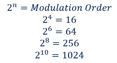
Modulation defines how many bits can be carried by a single RE irrespective of whether it’s useful bit or parity bits. 5G NR supports QPSK, 16 QAM, 64 QAM and 256 QAM modulation . With QPSK there are 2 bits can be transmitted per RE, with 16QAM it can be 4 bits, with 64QAM it can be 6 bits and with 256QAM it can 8 bits. These 16, 64 and 256 are know as modulation order of QAM Modulation and The no. of bits for each modulation order can be calculated using following formula.

Code Rate
Code rate can be defined as the ratio between useful bit and total transmitted bit (Useful + Redundant Bits). These Redundant bits are added for Forward Error Correction (FEC). In other words we can it is the ratio between the number of information bits at the top of the Physical layer and the number of bits which are mapped to PDSCH at the bottom of the Physical layer. We can also say, it a measure of the redundancy which is added by the Physical layer. A low coding rate corresponds to increased redundancy.

5G NR Modulation and Coding Scheme (MCS) Characteristics
- Modulation and Coding Scheme (MCS) defines the numbers of useful bits per symbols
- MCS selection is done based on radio condition and BLER
- MCS is change by gNB based on link adaptation algorithm
- MCS information is provided to UE using DCI
- 5G NR supports QPSK,16 QAM, 64 QAM and 256 QAM modulation for PDSCH
- There are about 32 MCS Indexes (0-31) are defined and MCS Index 29,30 and 31 are reserved and used for re-transmission
- 3GPP Specification 38.214 has given three tables for PDSCH MCS namely 64 QAM Table, 256 QAM Table and Low Spectral Efficiency 64 QAM Table
Modulation and Coding Scheme Tables
- 64 QAM table may be used when gNB or UE is not supporting 256 QAM or in poor radio condition where 256 QAM table decoding is not successful and gNB needs to allocated QPSK order modulation
- 256 QAM table may be used whenever 256QAM is to be allocated in very good radio conditions
- Low spectral efficiency (Low SE) 64 QAM table is suitable for applications which need reliable data transfer, e.g. applications belonging to the URLLC category. This table includes MCS which have low Spectral Efficiency i.e. a reduced coding rate which increase channel coding redundancy
64 QAM Table

256 QAM Table

Low SE 64 QAM Table

Which Table to select:
- gNB instructs the UE to select a specific MCS table using a combination of RRC signalling (IEs) and Phy layer signalling (RNTI).
- RRC signalling configure PDSCH-Config and SPS-Config parameter with the mcs-Table IE for a semi-static configuration which can be further modified using RRC signalling
- Phy layer uses a dynamic selection of the RNTI which scrambles the CRC bits belonging to the PDCCH payload, e.g. switching between the C-RNTI and MCS-C-RNTI can influence the selection of the MCS table.
MCS Table Selection Example:
With this example, we can show that MCS table selection initially configured with RRC signaling and further can be controlled using only Physical layer signaling.
- Consider a UE has been configured with parameter PDSCH-Config with mcs-Table = ‘qam256’ and allocated an MCS-C-RNTI alng with traditional a C-RNTI
- If the UE receives a PDSCH resource allocation using DCI 1_ 1 with the C-RNTI, then the UE will select the 256 QAM MCS table
- If the same UE receives a PDSCH resource allocation using DCT 1_ 0 with the C-RNTI, then UE will select the 64 QAM MCS table
- If the same UE receives a PDSCH resource allocation using either DCI 1_ 1 or 1 _ 0 with the MCS-C-RNTI, then the UE will select the Low SE table.
For Further Information
Please Contact Us