5G-NSA and 5G-SA networks compared

CableFree Remote Radio Head (RRH) used for 5G-SA and 5G-NSA networks

5G-NSA and 5G-SA network architecture compared

For leading mobile network operators (MNOs), 5G is mainly about offering high-speed connectivity to consumers, on devices that support fifth-gen (5G-NSA and 5G-SA) network services. To smoothly transition from the existing legacy core to 5G, MNOs have two pathways: Non-Standalone (NSA) or Standalone (SA) architecture. And while they are both means to the same end, NSA and SA are structurally and functionally different.

5G Networks:  5G-SA and 5G-NSA, SA, NSA architectures for modern mobile networks
5G Networks can be 5G-NSA or 5G-SA architecture

NSA allows operators to leverage their existing network investments in communications and mobile core instead of deploying a new core for 5G. 5G Radio Access Network (RAN) can be deployed and supported by the existing Evolved Packet Core (EPC), lowering CAPEX and OPEX. To further lower network operating costs, operators can adopt the virtualization of Control and User Plane Separation (CUPS) along with software-defined networking (SDN). These initial steps will help quickly unlock new 5G revenue streams and offer faster data speeds.

5G-SA is a completely new core architecture defined by 3GPP that introduces major changes such as a Service-Based Architecture (SBA) and functional separation of various network functions. Its architecture has the definite advantage of end-to-end high-speed and service assurance, particularly useful for MNOs who are set to commence new enterprise 5G services such as smart cities, smart factories, or other vertically integrated market solutions. The deployment model enables the rapid introduction of new services with quick time-to-market. However, it means additional investment and complexities of running multiple cores in the network.

Architecturally, NSA includes a new RAN, deployed alongside the 4G or LTE radio with the existing 4G Core or EPC. 5G SA, on the other hand, includes a new radio along with the 5G Core (5GC), comprising completely virtualized cloud-native architecture (CNA) that introduces new ways to develop, deploy, and manage services. 5GC supports high-throughput for accelerated performance than the 5G network demands. Its virtualized service-based architecture (SBA) makes it possible to deploy all 5G software network functions using edge computing.

5G-SA and 5G-NSA compared

5G Standalone (SA) vs 5G Non-Standalone (NSA)

5G-SA Architecture

According to a survey, 37% of MNOs will deploy 5G SA within two years; 27% of operators plan to deploy 5G SA within 12 to 18 months with an additional 10% increase within 24 months. 5G SA architecture will allow operators to address the fifth generation of mobile communications, including enhanced mobile broadband, massive machine-to-machine communications, massive IoT, and ultra-low latency communications.

CableFree Remote Radio Head (RRH) used for 5G-SA and 5G-NSA networks

Standalone 5G-NR comprises a new end-to-end architecture that uses mm-Waves and sub-GHz frequencies and this mode will not make use of the existing 4G LTE infrastructure. The SA 5G NR will use enhanced mobile broadband (eMBB), Ultra-Reliable and Low Latency Communications (URLLC), and huge machine-type communications (mMTC) to implement multi-gigabit data rates with improved efficiency and lower costs.

5G SA also enables more advanced network slicing capabilities, helping operators rapidly transition to both 5G New Radio (NR) and 5G as the core network. Network slicing, URLLC, and mMTC bring ultra-low latency along with a wide range of next-gen use cases like remote control of critical infrastructure, self-driving vehicles, advanced healthcare, and more. However, the NR advanced cases are not backward compatible with the EPC, which is the framework that provides converged voice and data on a 4G LTE network. The level of reliability and latency that 5G provides will be indispensable for handling smart-grid control machines, industrial automation, robotics, and drone control and coordination.

5G-NSA Architecture

NSA-5G NR is considered as the early version of SA 5G NR mode, in which 5G networks are supported by existing LTE infrastructure. It fundamentally concentrates on eMBB, where 5G-supported handsets and devices will make use of mmWave frequencies for increased data capacity but will continue to use existing 4G infrastructure for voice communications.

NSA helps MNOs launch 5G quickly for eMBB to get a competitive edge in the telecom market. NSA also helps leverage its existing LTE/VoLTE footprint to maximize the LTE installed base and boost capacity while increasing delivery efficiency. It will not support network slicing, URLLC, and mMTC, but its higher broadband speeds will enable services such as video streaming, augmented reality (AR), virtual reality (VR), and an immersive media experience.

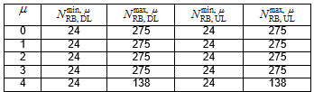
Non-Standalone 5G NR will provide increased data-bandwidth by using the following two new radio frequency ranges:

  • Frequency range 1 (450 MHz to 6000 MHz) – overlaps with 4G LTE frequencies and is termed as sub-6 GHz. The bands are numbered from 1 to 255.
  • Frequency range 2 (24 GHz to 52 GHz) – is the main mmWave frequency band. The bands are numbered from 257 to 511.

Technical Differences between 5G SA and 5G NSA

The main difference between NSA and SA is that NSA provides control signaling of 5G to the 4G base station, whereas in SA the 5G base station is directly connected to the 5G core network and the control signaling does not depend on the 4G network. In simple terms, NSA is like adding a solid-state drive to an old computer, which can improve the system’s performance, while SA is like replacing it with a new computer that has newer technologies and optimum performance.

Some benefits include:

  • 5G-NSA is a low-cost update of core compared to a 5G Core needed for 5G-SA.
  • 5G-NSA eases 5G network deployments as it reuses existing 4G facilities, thus allowing rapid time to market for 5G mobile broadband.
  • With NSA, the deployment is faster and time-to-market is lower, as 4G locations can be used to install 5G radio. SA requires building 5G base stations and the back-end 5G core network to fully realize the characteristics and functions of 5G.
  • SA involves a 5G core with SBA for scalability and flexibility to deliver a superfast network with ultra-low latency for advanced 5G use cases.

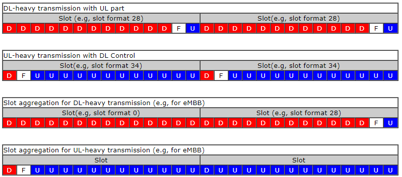
5G Usage Scenarios in NSA and SA Operation

The requirements of 5G NR for the SA provide a complete set of specifications for the 5G core network that goes beyond NSA. The three major usage scenarios defined for 5G by the 3GPP and GSMA include:

  1. Enhanced mobile broadband (eMBB)
  2. Ultra-reliable and low latency communications (URLLC)
  3. Massive machine-type communications (mMTC)

Future 5G Networks Include both NSA and SA

Early adopters of 5G primarily focus on 5G-NSA deployments as they compete to deliver 5G speeds with a quick time to market. These MNOs can move to SA-based architecture over a period of time, which most plan to do. 5G-NSA deployment remains a mainstream solution given its ability to handle both 4G- and 5G-based traffic, keeping these early adopters ahead of their competition as they undertake their network transformation. 5G devices are not widespread so the need for 5G-SA-based architecture is still nascent.

For the future, the convergence of NSA and SA will help operators move to a full 5G network. A complete virtualized 5G architecture will allow MNOs to migrate and choose varied functionalities of their existing NSA solution to the 5GC platform, as new 5G services are launched, allowing them to monetize their investment gradually rather than move all at once and enabling them to recover their costs over time.

Although 5G-SA is a more mature network architecture compared to 5G-NSA, NSA will continue to be the more commonly chosen path to 5G. All NSA single-mode 5G phones launched this year or early next year will be valid for a decade, and as SA architecture permeates, more and more 5G-SA devices will be in our homes and businesses.

For Further Information

Please Contact Us

5G NR PRACH function, contents and mapping

Explaining 5G NR PRACH function, contents and mapping

PRACH is used to carry random access preamble from UE towards gNB (i.e. 5G NR base station).
• It helps gNB to adjust uplink timings of the UE in addition to other parameters.
• Zadoff chu sequences are used to generate 5G NR random access preamble similar to LTE technology.
• Unlike LTE, 5G NR random access preamble supports two different sequence lengths with various format configurations as shown in the figure. The different formats help in wide deployment scenarios.

Random Access Preamble

5G NR PRACH function, contents and mapping with random access preamble
A: Long sequence of length 839
B: Short sequence of length 139
s: Zadoff chu sequence

Long Sequence

The 839 long sequence uses four preamble formats like LTE. These formats are designed for large cell deployment in FR1 (Sub-6 GHz range). They use subcarrier spacing of 1.25 KHz or 5 KHz.

Short Sequence

The 139 short sequence uses nine preamble formats. These formats are designed for small cell deployment including indoor coverage. These preamble formats are used for both FR1 (sub-6 GHz) and FR2 (mmwave) ranges. In FR1, it supports 15 or 30 KHz where as in FR2, it supports 60 or 120 KHz. subcarrier spacing.

5G NR PRACH physical layer processing

• PRACH uses same FFT as used for data.
• OFDM baseband signal generation for PRACH is defined in 3GPP TS 38.211 section 5.3.2.
• Engineers often come across situations (test cases) in which UE does not receive response from gNB for the PRACH message transmitted by it. During such scenarios, they need to analyze the test case with respect to various layers such as radio link, physical layer (L1) and last upper layer messages. This helps them diagnose the radio network issues and find root cause of any problems reported.

For Further Information on 5G Technology

Please Contact Us

5G-NR RACH Preamble Types: Long and Short Preambles

Understanding 5G-NR RACH Preamble Types: Long and Short Preambles

A preamble is send by UE to gNB over PRACH channel to obtain the UL synchronization. Similar to LTE, in 5G NR there are 64 preambles defined in each time-frequency PRACH occasion. The preamble consists of two parts cyclic prefix (CP) and Preamble Sequence.

5G-NR RACH Preamble Types: Long and Short Preambles

In 5G NR, there are 13 types of preamble format supported known as Format 0, Format 1, Format 2,Format 3,Format A1,Format A2,Format A3,Format B1, Format B2, Format B3, Format B4, Format C0, Format C1. These 13 types of preamble format can be grouped into two categories:

  • Long  Preamble
  • Short  Preamble

Differences in the time domain of different preamble formats includes different CP length, Sequence Length, GP length and number of repetitions can be seen in below picture.

5G-NR RACH Preamble Types: Long and Short Preambles

Long Preamble Characteristics 

  • Long preambles are based on a sequence length L=839
  • Sub-carrier spacing for long preambles can be either 1.25 Khz or 5 Khz
  • Numerology used for long preambles is  different from any other NR transmissions
  • Origin of long preambles partly from the preambles used for LTE
  • Long preambles can only be used for FR1 frequency bands which is below 6 Ghz
  • There are four different formats for the long preamble name Format#0, Format#1, Format#2 and Format#3
  • The preamble format is part of the cell random-access configuration and each cell is limited to a single preamble format
  • NR preamble format 0 and 1 are identical to the LTE preamble formats 0 and 2
  • A long preamble with 1.25 kHz numerology occupies six resource blocks in the frequency domain, while a preamble with 5 kHz numerology occupies 24 resource blocks
5G-NR RACH Preamble Types: Long and Short Preambles

Short Preamble Characteristics

  • Short preambles are based on a sequence length L=139
  • The sub-carrier spacing for short preambles is aligned with the normal NR sub-carrier spacing i.e. 15Khz, 30Khz, 60Khz and 120Khz.
  • Short preambles use a sub-carrier spacing of:
    • 15 Khz or 30 Khz in the case of operation below 6 Ghz (FR1)
    • 60 Khz or 120 Khz in the case of operation in the higher NR frequency bands (FR2).
  • A short preamble occupies 12 resource blocks in the frequency domain regardless of the preamble numerology
  • The short preambles are, in general shorter than the long preambles and often span only a few OFDM symbols
  • Short preambles formats are designed such that the last part of each OFDM symbol acts as a CP for the next OFDM symbol and the length of a preamble OFDM symbol equals the length of data OFDM symbols
  • In most cases it is therefore possible to have multiple preamble transmissions multiplexed in time within a single RACH slot (occasion). In other words, for short preambles there can may be multiple RACH occasions in the frequency domain as well as in the time domain within a single RACH slot .
  • 5G NR supports  mix of the “A” and “B” formats to enable additional formats like  A1/B1, A2/B2, and A3/B3.
  • Short preamble formats A and B  are identical except for a somewhat shorter cyclic prefix for the B formats.
  • Preamble formats B2 and B3  are always used in combination with the corresponding A formats (A2 and A3)
  • Short preambles are design to targeting the small/normal cell and indoor deployment scenarios
  • Short preambles  allows the gNB receiver to use the same fast Fourier transform (FFT) for data and random-access preamble detection.
  • These preambles are composition of multiple shorter OFDM symbols per PRACH preamble,makes them more robust against time varying channels and frequency errors.
  •  Short preambles supports analog beam sweeping during PRACH reception such that the same preamble can be received with different beams at the gNB

For Further Information on 5G-NR

Please Contact Us

Spectral Efficiency : 5G-NR and 4G-LTE compared

5G Networks

Spectral efficiency is an important consideration for 5G-NR radios, as it was for 4G/LTE: The amount of information that fits in a given channel bandwidth or one just say how efficiently can that piece of spectrum be used to transmit information.

There is a hard limit to how much data can be transmitted in a given bandwidth – this limit is well-known as the Shannon-Hartley Theorem and commonly referred to as the Shannon limit.

Spectral efficiency is usually expressed as “bits per second per hertz,” or bits/s/Hz, defined as the net data rate in bits per second (bps) divided by the bandwidth in hertz. Net data rate and symbol rate are related to the raw data rate which includes the usable payload and all overhead.

  • raw data rate = Payload + Overhead
  • net data rate = raw data rate – overhead
  • Spectral efficiency = net data rate in bps / Channel Bandwidth in Hz

For example, a system uses channel bandwidth as 2 MHz and it can support a raw data rate of say 15 Mbps, assuming 2 Mbps as overhead then net date rate will be as 13 Mpbs, then its spectrum efficient can be calculated as follows:

  • Spectral efficiency= 13 x 10^6 / 2 x 10^6 = 6.5 bits/second/Hz

Calculating Spectral Efficiency for LTE:

An LTE system can support a maximum channel bandwidth as 20 MHz (Not including Carrier Aggregation). Its symbol rate can be calculated as

  • Symbols/Second = 1200 x 14 x 1000 = 16,800,000 Symbols/Second

Considering 64-QAM as highest modulation for downlink each symbol can carries 6 bits provide raw data rate  as follows:

  • raw data rate = 16,800,000 x 6 = 100.8 Mbps (No MIMO considered)

Consider 4×4 MIMO: theoretically it makes raw data rates  four times i.e. 400 Mbps. assuming 25 % as overhead the net data rate will be as 300 Mbps. Similarly data rate can be calculated for uplink . In a 1×1 LTE uplink there is no MIMO, so Max raw data can be 100 Mbps with 64-QAM support in Uplink and after deducted 25% overhead net data rate for uplink will be 75 Mbps. Uplink net date with 16-QAM will be 51 Mbps.

  • Downlink Spectral Efficiency = 300 x 10^6 bps  / 20 x 10^6 Hz = 15 bits/second/Hz
  • Uplink Spectral Efficiency (64-QAM UL) = 75  x 10^6 bps  / 20 x 10^6 Hz = 3.75 bits /second / Hz
  • Uplink Spectral Efficiency (16-QAM UL) = 51  x 10^6 bps  / 20 x 10^6 Hz = 2.55 bits /second / Hz

Calculating Spectral Efficiency for 5G New Radio:

5G New Radio is capable of providing a downlink throughput 2.31 Gbps and uplink throughput of  2.47 Gbps with certain configuration shown below assuming 100 MHz channel bandwidth. (Single carrier component)

Spectral Efficiency of 5G-NR radio
  • Downlink Spectral Efficiency = 2.31 x 10^9 bps  / 100 x 10^6 Hz = 23 bits/second/Hz
  • Uplink Spectral Efficiency = 2.47  x 10^9 bps  / 100 x 10^6 Hz = 24 bits /second / Hz

Note: The values shown here are just theoretical value considering sensible baseline assumptions. Real-world network performance may differ.

For Further Information

For more information on Spectral Efficiency of 5G-NR radios,

Please Contact Us

5G NR Modulation and Coding Scheme – Modulation and Code Rate

5G-NR Modulation and Coding as used by 5G Base Stations (gNodeb) and CPE devices:

For any communication technology, Modulation and Coding Scheme (MCS) defines the numbers of useful bits which can carried by one symbol. In contrast with 5G or 4G, a symbol is defined as Resource Element (RE) and MCS defined as how many useful bits can be transmitted per Resource Element (RE) . MCS depends on radio signal quality in wireless link, better quality the higher MCS and the more useful bits can be transmitted with in a symbol and bad signal quality result in  lower MCS means less useful data can be transmitted with in a symbol.

In other words, we can say MCS depends  Blocker Error Rate (BLER). Typically there is a BLER threshold defined that equal to 10%. To maintain BLER not more than this value in varying radio condition Modulation and Coding Scheme (MCS) is allocated by gNB using link adaptation algorithm. The allocated MCS is signalled to the UE  using DCI over PDCCH channel e.g. DCI 1_0DCI 1_1

MCS basically defines the following two aspects:

  • Modulation
  • Code rate

Modulation

Modulation defines how many bits can be carried by a single RE  irrespective of whether it’s useful bit or parity bits. 5G NR supports QPSK, 16 QAM, 64 QAM and 256 QAM modulation . With QPSK there are 2 bits can be transmitted per RE, with 16QAM  it can be 4 bits, with 64QAM it can be 6 bits and with 256QAM it can 8 bits. These 16, 64 and 256 are know as modulation order of QAM Modulation and The no. of bits for each modulation order can be calculated using following formula.

Code Rate 

Code rate can be defined as the ratio between useful bit and total transmitted bit (Useful + Redundant Bits).  These Redundant bits are added for Forward Error Correction (FEC). In other words we can it is the ratio between the number of information bits at the top of the Physical layer and the number of bits which are mapped to PDSCH at the bottom of the Physical layer. We can also say, it  a measure of the redundancy which is added by the Physical layer. A low coding rate corresponds to increased redundancy.

5G NR Modulation and Coding Scheme (MCS) Characteristics 

  • Modulation and Coding Scheme (MCS) defines the numbers of useful bits per symbols
  • MCS selection is done based on radio condition and BLER
  • MCS is change by gNB based on link adaptation algorithm
  • MCS information is provided to UE using DCI
  • 5G NR supports QPSK,16 QAM, 64 QAM and 256 QAM modulation for PDSCH
  • There are about 32 MCS Indexes  (0-31) are defined and MCS Index 29,30 and 31 are reserved and used for re-transmission
  • 3GPP Specification 38.214 has given three tables for PDSCH MCS namely 64 QAM Table256 QAM Table and Low Spectral Efficiency 64 QAM Table

Modulation and Coding Scheme Tables

  • 64 QAM table may be used when gNB or UE is not supporting 256 QAM or in poor radio condition where 256 QAM table decoding is not successful and gNB needs to allocated QPSK order modulation
  • 256 QAM table may be used whenever 256QAM is to be allocated in very good radio conditions
  • Low spectral efficiency (Low SE) 64 QAM table is suitable for applications which need reliable data transfer, e.g. applications belonging to the URLLC category. This table includes MCS which have low Spectral Efficiency  i.e. a reduced coding rate which increase channel coding redundancy

64 QAM Table

5G NR Modulation and Coding Scheme – Modulation and Code Rate

256 QAM Table

5G NR Modulation and Coding Scheme – Modulation and Code Rate

Low SE 64 QAM Table

Which Table to select:

  • gNB instructs the UE to select a specific MCS table using a combination of RRC signalling (IEs) and Phy layer signalling (RNTI).
  • RRC signalling configure PDSCH-Config and SPS-Config parameter with the mcs-Table IE  for a semi-static configuration which can be further modified using RRC signalling
  • Phy layer uses a dynamic selection of the RNTI which scrambles the CRC bits belonging to the PDCCH payload, e.g. switching between the C-RNTI and MCS-C-RNTI can influence the selection of the MCS table.

MCS Table Selection Example:

With this example,  we can show that MCS table selection initially configured with RRC signaling and further can be controlled using only Physical layer signaling.

  • Consider a UE has been configured with parameter PDSCH-Config with mcs-Table ‘qam256’ and allocated an MCS-C-RNTI alng with traditional a C-RNTI
  • If the UE receives a PDSCH resource allocation using DCI 1_ 1 with the C-RNTI, then the UE will select the 256 QAM MCS table
  • If the same UE receives a PDSCH resource allocation using DCT 1_ 0 with the C-RNTI, then UE will select the 64 QAM MCS table
  • If the same UE receives a PDSCH resource allocation using either DCI  1_ 1 or 1 _ 0 with the MCS-C-RNTI, then the UE will select the Low SE table.

For Further Information

Please Contact Us

5G Disaggregated Network Topology Split Options

Functional Split Options for gNodeB 5G-NR Base Stations

A major benefit of 5G for Mobile Network Operators (MNOs) is the prospect of migrating from custom network nodes to a far more flexible approach that enables network nodes to be implemented in software running on generic hardware platforms. In the core network, this process is in an advanced state, with virtualisation and orchestration techniques from the IT world now being used to deploy network functions automatically at a large scale. The functional “split” is key to achieving efficiency gains.

The process is significantly more difficult in the RAN and backhaul network, and the prize for MNOs is greater here as these functions typically account for 70-80% of Capex. In Release 15, the 3GPP identified various functional splits in the 5G NR RAN gNodeB (base station) that would facilitate this process, identifying eight possible places where the gNodeB function could be split into separate functional units. The most popular of these “split” options are:

Split 0 – gNodeB Integrated Small Cell

The gNodeB is a traditional integrated 5G NR with the RF, PHY and stack layers integrated into a single unit, with an NG interface to the 5GC Core Network.

Split 2 – 3GPP F1

The 3GPP defines this disaggregated RAN with separate (gNodeB-)CU and (gNodeB-)DU units with a high level split 2 using the 3GPP defined F1 interface. Split 2 is sometimes used in conjunction with a lower level splits 6, 7.2 and 8. This new 3GPP 5G RAN architecture introduces new terminology, interfaces and functional modules.

Split 6 – Small Cell Forum (SCF) nFAPI

The split 6 interface protocol is the Network FAPI (nFAPI), specified by the Small Cell Forum, where the MAC and PHY functions are physically separate.

Split 7.2 – O-RAN Open Fronthaul

A split 7 interface has been specified by the O-RAN Alliance, which has adopted the eCPRI interface as its basis. Whereas CPRI passes antenna samples using a proprietary protocol, eCPRI uses Ethernet.

Split 8

The split 8 interface is mainly being considered where there are legacy systems and existing hardware and cabling/fibre can be reused.

Industry Body Backed Split Option Definitions

3GPP specified the higher layer F1 interface, but additional interfaces at lower layer splits have also been specified by other industry bodies, and offer different relative advantages and disadvantages.

  • The Split 6 interface protocol is the Network FAPI (nFAPI), specified by the Small Cell Forum, where the MAC and PHY functions are physically separate.
  • The Split 7 interface has been specified by the O-RAN Alliance, which has adopted the eCPRI interface as its basis. Whereas CPRI passes digitised RF signals to the antenna using a proprietary serial protocol, eCPRI uses Ethernet. Moreover, in O-RAN fronthaul, it is frequency domain samples that are transported between the upper PHY and lower PHY, which leads to advantages.
  • The Split 8 interface is mainly being considered where there are legacy systems and existing hardware and cabling/fibre can be reused.

For Further Information

Please Contact Us

5G NR Frame Structure

Exploring the 5G NR Frame Structure used in 5G New Radio networks and 5G Radio equipment: including gNodeB and 5G CPE devices

Frame Structure

The 5G NR frame structure is defined by the 3GPP and here we present details of the NR Frame Structure that is specified in 3GPP specification (38.211).

Numerology – Subcarrier Spacing

Compared to LTE numerology (subcarrier spacing and symbol length), the most outstanding difference you can notice is that NR support multiple different types of subcarrier spacing (in LTE there is only one type of subcarrier spacing, 15 KHz). The types NR numerology is summarized in 38.211 and I converted the table into illustration to give you intuitive understanding of these numerology.

As you see here, each numerology is labeled as a parameter(u, mu in Greek). The numerology (u = 0) represents 15 kHz which is same as LTE. And as you see in the second column the subcarrier spacing of other u is derived from (u=0) by scaling up in the power of 2.

5G Frame Structure

Numerology and Slot Length

As illustrated below, Slot length gets different depending on numerology. The general tendency is that slot length gets shorter as subcarrier spacing gets wider. Actually this tendency comes from the nature of OFDM. You would see further details on how the slot length is derived in Radio Frame Structure section.

5G Frame Structure Slot

Numerology and Supported Channels

Not every numerology can be used for every physical channel and signals. That is, there is a specific numerologies that are used only for a certain type of physical channels even though majority of the numerologies can be used any type of physical channels. Following table shows which numerologies can be used for which physical channels.

< 38.300-Table 5.1-1: Supported transmission numerologies and additional info.>

OFDM Symbol Duration

Parameter / Numerlogy (u)01234
Subcarrier Spacing (Khz)153060120240
OFDM Symbol Duration (us)66.6733.3316.678.334.17
Cyclic Prefix Duration (us)4.692.341.170.570.29
OFDM Symbol including CP (us)71.3535.6817.848.924.46

Numerology – Sampling Time

Sampling time can be defined differently depending on Numerogy (i.e, Subcarrier Spacing) and in most case two types of Timing Unit Tc and Ts are used.

  • Tc = 0.509 ns
  • Ts = 32.552 ns

See Physical Layer Timing Unit page to see how these numbers are derived and to see some other timing units.

Radio Frame Structure

As described above, in 5G/NR multiple numerologies(waveform configuration like subframe spacing) are supported and the radio frame structure gets a little bit different depending on the type of the numerology. However, regardless of numerology the length of one radio frame and the length of one subfame is same.  The length of a Radio Frame is always 10 ms and the length of a subframe is always 1 ms. 

What changes to accommodate the physical property of the different numerology ? Answer is to put different number of slots within one subfame. There is another varying parameter with numerology. It is the number of symbols within a slot. However, the number of symbols within a slot does not change with the numerology, it only changes with slot configuration type. For slot configuration 0, the number of symbols for a slot is always 14 and for slot configuration 1, the number of symbols for a slot is always 7.

Now look at details of radio frame structure for each numerology and slot configuration:

< Normal CP, Numerology = 0 >

In this configuration, a subframe has only one slot in it, it means a radio frame contains 10 slots in it. The number of OFDM symbols within a slot is 14.

5G radio frame structure

< Normal CP, Numerology = 1 >

In this configuration, a subframe has 2 slots in it, it means a radio frame contains 20 slots in it. The number of OFDM symbols within a slot is 14.

< Normal CP, Numerology = 2 >

In this configuration, a subframe has 4 slots in it, it means a radio frame contains 40 slots in it. The number of OFDM symbols within a slot is 14.

< Normal CP, Numerology = 3 >

In this configuration, a subframe has 8 slots in it, it means a radio frame contains 80 slots in it. The number of OFDM symbols within a slot is 14.

< Normal CP, Numerology = 4 >

In this configuration, a subframe has 16 slots in it, it means a radio frame contains 160 slots in it. The number of OFDM symbols within a slot is 14.

< Extended CP, Numerology = 2 >

In this configuration, a subframe has 8 slots in it, it means a radio frame contains 80 slots in it. The number of OFDM symbols within a slot is 12.

Slot Format

Slot Format indicates how each of symbols within a single slot is used. It defines which symbols are used for uplink and which symbols are used for downlink within a specific slot. In LTE TDD, if a subframe (equivalent to a Slot in NR) is configured for DL or UL, all of the symbols within the subframe should be used as DL or UL. But in NR, the symbols within a slot can be configured in various ways as follows.

  • We don’t need to use every symbols within a slot (this can be a similar concept in LAA subframe where only a part of subframes can be used for data transmission).
  • Single slot can be devided into multiple segments of consecutive symbols that can be used for DL , UL or Flexible.

Theoretically we can think of almost infinite number of possible combinations of DL symbol, UL symbol, Flexible Symbol within a slot, but 3GPP allows only 61 predefined symbol combination within a slot as in following table. These predefined symbol allocation of a slot called Slot Format. (For the details on how these Slot Format is being used in real operation, refer to Slot Format Combination page).

<38.213 v15.7 -Table 11.1.1-1: Slot formats for normal cyclic prefix>

D : Downlink, U : Uplink, F : Flexible

 Symbol Number in a slot
Format012345678910111213
0DDDDDDDDDDDDDD
1UUUUUUUUUUUUUU
2FFFFFFFFFFFFFF
3DDDDDDDDDDDDDF
4DDDDDDDDDDDDFF
5DDDDDDDDDDDFFF
6DDDDDDDDDDFFFF
7DDDDDDDDDFFFFF
8FFFFFFFFFFFFFU
9FFFFFFFFFFFFUU
10FUUUUUUUUUUUUU
11FFUUUUUUUUUUUU
12FFFUUUUUUUUUUU
13FFFFUUUUUUUUUU
14FFFFFUUUUUUUUU
15FFFFFFUUUUUUUU
16DFFFFFFFFFFFFF
17DDFFFFFFFFFFFF
18DDDFFFFFFFFFFF
19DFFFFFFFFFFFFU
20DDFFFFFFFFFFFU
21DDDFFFFFFFFFFU
22DFFFFFFFFFFFUU
23DDFFFFFFFFFFUU
24DDDFFFFFFFFFUU
25DFFFFFFFFFFUUU
26DDFFFFFFFFFUUU
27DDDFFFFFFFFUUU
28DDDDDDDDDDDDFU
29DDDDDDDDDDDFFU
30DDDDDDDDDDFFFU
31DDDDDDDDDDDFUU
32DDDDDDDDDDFFUU
33DDDDDDDDDFFFUU
34DFUUUUUUUUUUUU
35DDFUUUUUUUUUUU
36DDDFUUUUUUUUUU
37DFFUUUUUUUUUUU
38DDFFUUUUUUUUUU
39DDDFFUUUUUUUUU
40DFFFUUUUUUUUUU
41DDFFFUUUUUUUUU
42DDDFFFUUUUUUUU
43DDDDDDDDDFFFFU
44DDDDDDFFFFFFUU
45DDDDDDFFUUUUUU
46DDDDDFUDDDDDFU
47DDFUUUUDDFUUUU
48DFUUUUUDFUUUUU
49DDDDFFUDDDDFFU
50DDFFUUUDDFFUUU
51DFFUUUUDFFUUUU
52DFFFFFUDFFFFFU
53DDFFFFUDDFFFFU
54FFFFFFfDDDDDDD
55DDFFFUUUDDDDDD
62-254Reserved
255UE determines the slot format for the slot based on tdd-UL-DL-ConfigurationCommon, or tdd-ULDL-ConfigurationDedicated and, if any, on detected DCI formats

Why we need so many different types of slot formats ? Key goal is to make NR scheduling flexible especially for TDD operation. By applying a slot format or combining different slot formats in sequence, we can implement various different types of scheduling as in the following example:

TDD DL/UL Common Configuration

See  TDD DL/UL Common Configuration page.

Resource Grid

The resource grid for NR is defined as follows. If you just take a look at the picture, you would think it is almost identical to LTE resource grid. But the physical dimension (i.e, subcarrier spacing, number of OFDM symbols within a radio frame) varies in NR depending on numerology.

5G NR Frame

The maximum and minimum number of Resource blocks for downlink and uplink is defined as below (this is different from LTE)

< 38.211 v1.0.0 Table 4.4.2-1: Minimum and maximum number of resource blocks.>

Following is the table that I converted the downlink portions of Table 4.4.2-1 into frequency Bandwidth just to give you the idea on what is the maximum RF bandwidth that a UE / gNB need to support for single carrier.

umin RBMax RBsub carrier spacing(kHz)Freq BW min(MHz)Freq BW max(MHz)
024275154.3249.5
124275308.6499
2242756017.28198
32427512034.56396
42413824069.12397.44

SS/PBCH

SS(PSS and SSS) and PBCH in NR is transmitted in the same 4 symbol block as specified in the following table.

< Frequency Domain Resource Allocation >

Overall description on the resource allocation for SS/PBCH block is described in 38.211 – 7.4.3.1 Time-frequency structure of an SS/PBCH block and followings are the summary of the specification.

  • SS/PBCH block consists of 240 contiguous subcarriers (20 RBs)
  • The subcarriers are numbered in increasing order from 0 to 239 within the SS/PBCH block
  • The UE may assume that the contents(value) of the resource elements denoted as ‘Set to 0’ in Table 7.4.3.1-1 are set to zero. (This mean that the contents of the gray colored resource element in the SSB diagram shown below is filled with zeros).
  • k_ssb corresponds to the gap between Subcarrier 0 of SS/PBCH block and Common Resource Block 
    • is obtained from the higher-layer parameter OffsetToPointA
    • offset-ref-low-scs-ref-PRB corresponds to the FrequencyInfoDL.absoluteFrequencyPointA. Data type is ARFCN-ValueNR and the range of the value is INTEGER (0..3279165) in integer.
  • There are two types of SS/PBCH Block
    • Type A (Sub 6)
      • k_ssb(k0 in older spec) = {0,1,2,…,23}
        • 4 LSB bits of k_ssb value can informed to UE via ssb-subcarrierOffset in MIB
        • The MSB bit is informed to UE via a bit within the PBCH Data ()  
        • is expressed in terms of 15 Khz subcarrier spacing
      • u (numerology) = {0,1}, FR1 (sub 6 Ghz)
      • is expressed in terms of 15 Khz subcarrier spacing
    • Type B (mmWave)
      • k_ssb(k0 in older spec) = {0,1,2,…,11}
        • the whole k_ssb value can be informed to UE via ssb-subcarrierOffset in MIB
        • is expressed in terms of the subcarrier spacing provided by the higher-layer parameter subCarrierSpacingCommon in MIB  .
      • u (numerology) = {3,4}, FR2 (mmWave)
      • is expressed in terms of 60 Khz subcarrier spacing

NOTE : Actually understanding k_ssb and  in the resource grid often get confusing and hard to visualize. The following is an example where the SubcarrierSpacingCommon is equal to 30KHz, and k_ssb=2, where in such a case the center of the first subcarrier of the SS/PBCH Block (which has 15KHz SCS) coincides with the center frequency of the subcarrier 1 of    

5G NR Frame

This table can be represented in Resource Grid as shown below. Note that the position of PBCH DM-RS varies with v and the value v changes depending on Physical Cell ID.

5G NR Frame

< Time Domain Resource Allocation >

Following table indicates the first OFDM symbol number (s) where SS/PBCH is transmitted. This is based on 38.213 – 4.1 Cell Search.

The document states as follows :

  • For a half frame with SS/PBCH blocks, the number and first symbol indexes for candidate SS/PBCH blocks are determined according to the subcarrier spacing of SS/PBCH blocks as follows.

This means that [38.213 – 4.1 Cell Search] specifies SS/PBCH location in time domain as illustrated below.

5G NR Frame

< Start Symbols for each subcarrier spacing and frequency >

5G NR Frame

Followings are examples of SSB Transmission for each cases. For the simplicity, I set the frequency domain location of SSB block to be located at the bottom of the system bandwidth, but in reality the frequency domain location can change to other location (e.g, center frequency of the system bandwidth). The main purpose of these examples is o show the time domain location (transmission pattern) of each cases. In real deployment, it is highly likely (but not necessarily) that the frequency domain location of the SSB located around the center frequency.

The example below shows how you can correlate the above table to the SSB transmission plot shown in the following examples.

5G NR Frame
5G NR Frame

For Further Information

For more information about 5G NR Frame structure used in 5G Radios:

Please Contact Us

Safety of 5G Frequencies and Networks

Massive MIMO Beamforming 5G

Is 5G Safe? Why do some people think it isn’t?

There’s currently huge controversy in the news today regarding safety of 5G: Is it safe, or not? 5G vendors & scientists say the technology is perfectly safe, and some members of the public allege that 5G isn’t safe. Here we examine the topics factually.

Frequencies used by 5G

There is nothing magic or new about the frequencies used or proposed for 5G. They have ALL been used already, actually for decades! 5G frequencies are split into two sections: FR1 (less than 6GHz) and FR2 (high frequency microwave, or “millimeter wave”).

Almost ALL of the FR1 frequencies have already been used for 4G, and some before that for 3G, and 2G, back to the 1990’s. A good example is 900MHz (the original GSM system) and 1800MHz (second round of GSM). 2100MHz was used extensively for 3G. A few of the FR1 frequencies haven’t been used for 4G before (e.g. 3800 up to 4200MHz) but they have been used for other purposes before.

FR2 frequencies (millimeter wave, or mmWave) have already been used – very widely – for Point-to-Point microwave links. All of the FR2 bands (24Ghz, 26GHz, 28GHz, 38-40GHz, and even the proposed 60GHz) have been used for point-to-point terrestrial microwave links. Those are the parabolic dishes you see everywhere on rooftops or towers. These signals are highly directional “pencil beams” with typically 1 degree or less beam width. The number of these links globally is in the 100,000+ range: they are beaming signals around cities all over the world, usually connecting internet services, beaming signals up to 3G/4G towers or for links between corporate office networks. As a result of the creation of 5G technology, these frequencies are now being re-used (“re-farmed”) for use by 5G base stations to connect end users to the internet, using Point-to-multipoint beamforming technologies. Important note: the use of 5G is no more or less “scary” than the previous use for point to point links. Note that point-to-point microwave has existed since 1930: 90 years ago, and health risks (and lack of risk to public) are very well understood.

Operating Distances

5G in lower frequencies travels longer distances than higher frequencies, due to laws of physics. This is why the lower frequencies are used for Rural locations for wide area coverage, whereas the higher frequencies are reserved for use in cities, where distances are shorter, and user densities higher.

Also, the lower frequencies (lower end of FR1) can be transmitted at higher power levels than the higher frequencies. Conversely, high frequencies (mmWave, FR2) are limited to lower power due to limitation of today’s commercial technology.

5G in the 24GHz, 26GHz, 28GHz range and above (also called millimeter wave, or mmWave bands) uses higher frequencies than 4G. As a result, these high frequency 5G signals are not capable of traveling large distances (over a few hundred meters), unlike 4G or lower frequency 5G signals (sub 6 GHz) so penetration and hence coverage are lower.
This higher frequency therefore requires placing 5G base stations every few hundred meters in order to use higher frequency bands.

5G and RF power levels

Some of the “5G Conspiracists” allege that 5G will cause damage/health risk to humans. There is simply no measured case or evidence of this happening. If there were, there would be scientists & health advisors demanding change. Let’s examine in more detail:

5G sites using FR1 transmit at exactly the SAME power levels as 4G sites. So you’re not irradiated any more than a 4G site was. 40W a typical figure for a macro (big) site, and 1W for a Small Cell (small site).
Note carefully: 5G FR1 sites use EXACTLY the same power levels as 4G sites, which is similar to 3G sites, and before that, 2G sites …
5G uses “sector antennas” (typically 3 on a macro site) just like 4G does.
Therefore any related health risk is therefore the same for 5G as it’s predecessors.

5G sites using FR2 transmit at MUCH lower power levels: less than 1 Watt typically. These high frequency signals have poor penetration of buildings and obstacles, so are generally “line of sight” only. As noted above, ALL of the FR2 frequencies have been used before, for terrestrial microwave links, and at similar power levels (less than 1 Watt).
The use of beamforming steers the signal to the required locations; this reduces the overall amount of transmitted power emitted into the air, and hence total radiation. Put simply, if you aren’t using your device, the base station doesn’t point power at you.

How to 5G power levels compare to other Radio/RF transmitters?

The VERY good question conspiracists & “truthers” never discuss. Let’s go straight there.

  • A TV transmitter such as Crystal Palace in London, UK currently transmits digital terrestrial Television at over 1200kW (1.2 MEGAWATT, or 1,200,000 watts), and has been transmitting TV since 1956.  That is 120 MILLION TIMES more power than a V-band 60GHz radio, and transmitting for over 60 years.   Did you hear “5G protesters” complaining about TV transmitters? No, because there’s no widespread history of health effects over 60 years .
  • Airport Radars:   To keep planes flying safely, airport radars transmit pulses up to 25kW (25 kilowatts, or 25,000 Watts) into the air, with average power 2.1kW (2100 Watts).  Interestingly, these signals are at similar frequencies to 3G, 4G and 5G.  In the USA, 2.7 – 2.9 GHz is used.  Yet nobody complains about these high power levels of radar, which has been in constant use since the 1930s:  90 years.
  • Digital Radio (DAB): Crystal Palace transmits digital radio with 18kW (18,000 Watts) of radio power. Compare that with 40W of a large (macro) 5G base station.
  • Emergency Service (TETRA) Radios : used by police, fire & ambulances: transmit at up to 45 Watts. Very similar to the 40W of a large (macro) 5G base station.

You will notice that the HIGHEST powered transmitters are Television transmitters (Megawatt), Radars & Radio stations (10’s of Kilowatts). A macro 5G base station at 40W comes nowhere close. Note that these various transmitters are used on different frequencies, there’s no “one” frequency that is safer (or less safe) than another. It’s only the RF exposure (power) level that matters – specifically, the power incident on your own human body.

Why is there no mass hysteria from “Truthers” about TV, Radar and Radio transmitters? Because if they were THAT bad for our health, they would have been banned and switched off decades ago. Evern the largest (macro) 5G transmit powers are tiny by comparison.

Key “Truther” points examined:

  • 60GHz is absorbed by Oxygen in the bloodstream (Untrue)
    Out in the open air this absorption is true : but not in the body! 60GHz signals are 40% reflected by skin surface, absorbed by water (body is 60% water), and does NOT enter the bloodstream. The “Truthers” invent Pseudo-science , claiming: “This causes Oxygen to not bind well to blood hemoglobin causing the body to become Oxygen starved (hypoxia)”  This statement is hopelessly unscientific.  The ultra low power 60GHz signals do not even penetrate human skin.  The signals are partly reflected and partly absorbed by the skin, preventing them entering the body and cannot cause the claimed effect.  There is NO scientific study which will back up this claimed hypoxia effect on the human body.  The “5G protesters” NEVER provide any, because there is no publication or science that would agree with their unscientific claims – it’s simply not impossible. They make stuff up to make you afraid, and sharing their website gives them more “hits”: Some have adverts on their sites. More clicks means more money for them! (Fear=money for some)
  • 5G is a state-sponsored weapon: Untrue.
    5G is simply a marketing term applied to the work of the 3GPP, a standards body which includes equipment vendors & operators, as a linear development of from work that was labelled 4G and 3G before it. Governments are not included in developing 2G, 3G, 4G, 5G… and future 6G technology – corporations are.
  • Governments want to use 5G to control the population: Untrue,
    in that 5G gives Government agencies no more data than 4G does. Your location, digital activities, content & data usage habits are already well known to Google, Facebook and – on warrant – Law Enforcement Agencies. 5G does not change this at all. You already gave all that data to companies 10 years ago when you bought a 3G smartphone, or signed up with Social Media sites, apps, Apple or Google services. Law enforcement agencies can demand access to that data with a warrant.
  • IoT is scary: Untrue, in any way that relates to 5G.
    “Internet of Things” is a marketing label applied to home gadgets – and industrial devices – that are connected via the Internet by either WiFi or cellular (4G, 5G) networks. The same IoT label applies to a WiFi doorbell. Main concern with IoT is DATA security, particularly physical security (locks, cars) and CCTV camera feeds. That has nothing to do with 5G, because the concern is the data security of the devices & security attitudes of companies that sell them. Note that the WiFi-connected IoT devices are a much greater security risk than 4G, 5G because WiFi is much easier for criminals to hack/spoof.
  • 5G causes cancer: Untrue.
    5G uses the same signals as 4G (FR1), plus some millimeter wave frequencies (FR2) which were previously used by microwave links for decades. There is no link to cancer in 30+ years of medical research and continued exposure to these signals. Microwave & radio signals used by 4G & 5G are NON-ionising radiation which is not hazardous except in massively high power levels (far more than 4G, 5G etc). The “dangerous” radiation type is IONISING radiation, including X-rays and similar. Those are not used for communication for this exact reason: they are dangerous.
    (Side-note: X-Rays used in medicine are VERY carefully controlled. Had an X-Ray? note the operators have shielding everywhere, because they use it every day & could get higher does than patients. They regulate the dose to you carefully for your safety)
  • 5G is linked to Coronavirus: Untrue.
    There’s no link at all. Many of the countries with terrible cases of Coronavirus have no 5G. And vice versa. All the theories connecting the two have been soundly debunked by reputable & international scientists.
    (Side note: there IS a link between Coronavirus deaths and air pollution: because the Coronavirus effect on the body attacks the lungs, putting patients with poor respiration are at great risk. Cleaning up diesel emissions, industrial cities & banning smoking would have saved 1000’s of lives from Coronavirus.)

Power levels and Distance (very important topic)

The RF power emitted from the transmitter antenna spreads with distance. This means that a person some distance away from the tower only receives a weak signal. As you DOUBLE the distance, you receive one QUARTER the power level. This is called the “inverse square law”. What it means in practice is that a person 100’s of metres away from a base station is radiated with only microwatts of power, which is insignificant, especially compared to this next point:

The highest radiation of Radio signals you will get is from …. wait for it …
Your cellphone is on your person – and when used in the worst case, held directly against your head. The cellphone transmits at up to 1 Watt power – in all directions – which means the signals go into your head as well as the air around you. This topic remains the same since the first cordless phones in the 1980’s, analogue cellphones and GSM phones in the 1990’s. Using the phone means the signal is close to your head – and the most sensitive item, your brain. The HIGHEST amount of radiation you will receive from any wireless system is from your OWN HANDSET when you hold it to your head to make a voice call. Therefore, if you are really worried about cellphone safety – STOP using your OWN phone. The radiation your body receives from it is 1000’s of times stronger than that you receive from the mast.

If you’re worried about 2G, 3G, 4G, 5G masts: stop now. The FIRST thing you must do is switch off your OWN phone, and never hold it against your head to talk. And if it’s in your pocket/jacket/handbag do remember, it’s still transmitting to the mast, updating it’s location to the network, and often up/downloading data to your apps continually. It’s still transmitting, even in “standby”.
If you’re not prepared to turn off your OWN PHONE, then stop worrying about masts at all. The signal from masts signal is over 1000 times weaker than your OWN PHONE when it reaches your body.

Massive MIMO Beamforming 5G
Diagram courtesy Qualcomm

5G FR2 mmWave Penetration

Also, these higher frequency 5G signals cannot penetrate solid objects easily, such as cars, trees, and walls, because of the nature of these higher frequency electromagnetic waves. 5G cells can be deliberately designed to be as inconspicuous as possible, which finds applications in places like restaurants and shopping malls.

Cell types
5G NR FR2
Deployment environmentMax. number ​of usersOutput power ​(mW)Max. distance from ​base station
FemtocellHomes, businessesHome: 4–8
Businesses: 16–32
indoors: 10–100
outdoors: 200–1000
10s of meters
Pico cellPublic areas like shopping malls,
airports, train stations, skyscrapers
64 to 128indoors: 100–250
outdoors: 1000–5000
10s of meters
Micro cellUrban areas to fill coverage gaps128 to 256outdoors: 5000−10000few hundreds of meters
Metro cellUrban areas to provide additional capacitymore than 250outdoors: 10000−20000hundreds of meters
Wi-Fi
(for comparison)
Homes, businessesless than 50indoors: 20–100
outdoors: 200–1000
few 10s of meters
5G NR mmWave FR2 coverage

Challenges for 5G Safety – for EVERYONE !

5G Networks
5G Networks

It is the responsibility of the 4G/5G cellular industry, national regulators, safety agencies and all academics to be truthful about the safety of all radio transmitters. There must be no cover-ups, lying, or partial truths. Medical research into possible risks of RF exposure must continue and be well funded. The industry needs to deliver reliable cellullar service without putting populations at risk. “Profit” cannot come at cost of public safety.

Conversely – “truthers” making up pseudo-science & invented “facts”, with blogs written by uneducated persons have so far resulted in:

  • Violence and threats against telecom employees doing their jobs on sites
  • 4G/5G sites being burned down (resulting in loss of service to Hospitals, including those treating Coronavirus and critical health conditions)
  • Death threats and threats of violence against business owners.

Now think clearly and rationally: EVERYONE has a legal & moral responsibility to behave within the law and not to threaten the health of others.
Clearly those posting non-factual “truther” content on Internet websites & social medahave a responsibility to bear. If you are one of those authors, think carefully. Your action could well cause harm or death of others.

I simply don’t believe you!

That’s the frequent response of someone when confronted with information that conflicts with their previously held opinion or prejudices. In the case of 5G, we have we have plenty of information sources. On the “5G is safe” side we have:

  • All reputable Scientists Worldwide
  • All national Governments
  • Biologists Worldwide
  • All safety Agencies Worldwide
  • The Cellphone industry
  • 30+ years of no measurable health effects of cellphones on worldwide population

And on the “5G is unsafe” side we have:

  • Conspiracists without facts
  • Non-scientific blog writers, some whom earn $ from adverts on their blogs (!)
  • Narcissists who want “likes” on posts, or TV appearances
  • Easily-swayed but highly opinionated people
  • NO evidence of health effects over 30+ years
  • NO reputable scientists !

Have a careful think about what sources of information you take in forming your world view. Just two hundred years ago, our ancestors burned and drowned innocent people for “witchcraft”. Why are we any better informed than our ancestors? Answer: SCIENCE and EDUCATION. We use logic, rather than irrational and uninformed fear.

Conclusion for 5G & Safety

There is a huge media frenzy and “truther sites” full of pseudo-science about 5G & safety. We suggest we make our decisions based on science and facts. Here’s our summary:

  • 5G is no less safe than 4G. If you didn’t protest 4G, stop protesting 5G.
  • (If you DID protest 4G, then carry on protesting, but remember, 5G is no less safe!)
  • Millimeter wave” frequencies have already been used for 3 decades or more for terrestrial microwave links. We’ve already been irradiated by them for 30+ years, with no harm to us. 5G just re-uses these same frequencies.
  • There is no measured health risk from “Millimeter Wave” signals in any credible study or publication. 60GHz doesn’t stop O2 in the blood, that’s a non-scientific myth invented by “truther” blogs. No medical reports or science to back up claims.
  • “Millimeter wave” (FR2) transmitters are on average 50x less powerful than the lower frequency FR1 macro (main site) transmitters.
  • The HIGHEST radiation you will get is from your OWN cellphone: it’s right next to your body, and transmits even in your pocket/jacket/handbag. If you’re worried, turn it off.
  • Turning off 5G transmitters on masts makes AlMOST NO DIFFERENCE because the 2G, 3G, 4G transmitters on the mast are still transmitting, all at very similar power levels and frequencies, and distance to you is the same. Power levels radiated to your body remains almost unchanged whether you turn 5G on or off.
  • Turning OFF all the cellphone masts will cause deaths. A LOT of them, as your loved ones can’t dial an ambulance, lost persons, persons caught in fires & crash victims can’t call help. Emergency responders also rely on the masts. Conversely, there’s no measured death rate from cellphone masts, in over 40 years of widespread use.
  • LOGIC as well as ETHICS says leave the masts turned on.

For Further Information

If you are interested in 5G Health & Safety:
Please Contact Us

5G Coverage using FR2 mmWave frequencies

Massive MIMO Beamforming 5G

5G FR2 Coverage and Penetration

5G in the 24GHz, 26GHz, 28GHz range and above (also called millimeter wave, or mmWave bands) uses higher frequencies than 4G. As a result, these high frequency 5G signals are not capable of traveling large distances (over a few hundred meters), unlike 4G or lower frequency 5G signals (sub 6 GHz) so penetration and hence coverage are lower.
This higher frequency therefore requires placing 5G base stations every few hundred meters in order to use higher frequency bands.

5G FR2 mmWave Penetration

Also, these higher frequency 5G signals cannot penetrate solid objects easily, such as cars, trees, and walls, because of the nature of these higher frequency electromagnetic waves. 5G cells can be deliberately designed to be as inconspicuous as possible, which finds applications in places like restaurants and shopping malls.

5G mmWave FR2 Penetration and Coverage
Diagram courtesy Qualcomm
Cell types
5G NR FR2
Deployment environmentMax. number ​of usersOutput power ​(mW)Max. distance from ​base station
FemtocellHomes, businessesHome: 4–8
Businesses: 16–32
indoors: 10–100
outdoors: 200–1000
10s of meters
Pico cellPublic areas like shopping malls,
airports, train stations, skyscrapers
64 to 128indoors: 100–250
outdoors: 1000–5000
10s of meters
Micro cellUrban areas to fill coverage gaps128 to 256outdoors: 5000−10000few hundreds of meters
Metro cellUrban areas to provide additional capacitymore than 250outdoors: 10000−20000hundreds of meters
Wi-Fi
(for comparison)
Homes, businessesless than 50indoors: 20–100
outdoors: 200–1000
few 10s of meters
5G NR mmWave FR2 coverage

Challenges for 5G Coverage:

Transmissions in mmWave bands suffer from significantly higher path loss and susceptibility to blockage. In addition, mmWave RF complexity makes meeting the cost and power constraints of mobile devices extremely challenging, which is why mmWave for mobile communications has historically been not feasible—until now. 5G NR mmWave is changing this.

Uses for 5G mmWave

While the initial focus for mobile operators is to quickly expand network capacities by starting deployments of 5G NR mmWave in existing dense urban markets, there are even more opportunities for mmWave beyond traditional macro networks. One area of interest is to bring mmWave indoors to address the exploding demand of fiber-like wireless broadband access in crowded venues, such as convention centers, concert halls, and stadiums. These venues have traditionally been challenged with limited network capacity, thereby constrained with the quality of service (e.g., slow speeds and unreliable connectivity) they can deliver. With mmWave’s significantly wider bandwidth and high spatial multiplexing gains, mobile operators and service providers could rapidly make multi-Gigabit, low-latency connectivity available to a large number of users.

Another exciting opportunity for mmWave is for private indoor enterprises, including offices, shop floors, meeting rooms and more. Imagine having virtually unlimited capacity and fiber-like wireless connectivity for your devices at work, no matter if it’s a smartphone, tablet, laptop, or mobile extended reality (XR). For these indoor deployment scenarios, we have also performed extensive study to show that significant coverage (i.e., >90%) and multi-Gbps median speeds can be achieved simply by co-siting mmWave small cells with existing LTE or Wi-Fi access points.

For Further Information

If you are interested in 5G Deployment Solutions:
Please Contact Us