GTP is used in LTE networks to carry user data – from GSM/GPRS, UMTS/3G, 4G/LTE and 5G:
GPRS Tunnelling Protocol User Plane (GTP-U): The GTP-U protocol is used over S1-U, X2, S4, S5 and S8 interfaces of the Evolved Packet System (EPS). GTP-U Tunnels are used to carry encapsulated T-PDUs and signalling messages between a given pair of GTP-U Tunnel Endpoints. The Tunnel Endpoint ID (TEID) which is present in the GTP header indicates which tunnel a particular T-PDU belongs to.
The transport bearer is identified by the GTP-U TEID and the IP address (source TEID, destination TEID, source IP address, destination IP address).
GTP is a fundamental workhorse of mobile user plane packet data.
GSM, UMTS, LTE & NR all have one protocol in common – GTP – The GPRS Tunneling Protocol.
So why do every generation of mobile data networks from GSM/GPRS in 2000, to 5G NR Standalone in 2020, rely on this one protocol for transporting user data
Why GTP? GTP – the GPRS Tunnelling Protocol, is the protocol which encapsulates and tunnels IP packets from the internet / packet data network, to and from the User.
Why encapsulate the packets? What if the Base Station had access to the internet and routed the traffic to the users?
If we were to do that, we would have to have large pools of IP addresses available at each Base Station and when a user connected they’d be assigned an IP Address and traffic for these users would be routed to the Base Station which would forward it onto the user.
This would work well until a user moves from one Base Station to another, when they’d have to get a new IP Address allocated.
TCP/IP was never designed to be mobile, as an IP address only exists in a single location.
Breaking out traffic directly from a base station would have other issues, such as no easy way to enforce QoS or traffic policies, meter usage, etc.
How we solve IP’s lack of mobility? GTP
GTP addressed the mobility issue by having a single fixed point the IP Address is assigned to (in GSM/GRPS/UMTS this is the Gateway GPRS Support Node, in LTE this is the P-GW and in 5G-SA this is the UPF), which encapsulates IP traffic to/from a mobile user into GTP Packet.
In some ways GTP is like GRE or any of the other common encapsulation protocols, wrapping up the IP packets into a GTP packet which we can rerouted to different Base Stations as the users move from being served by one Base Station to another.
This ease-of-redirecting / rerouting of user traffic is why GTP is used for NR (5G), LTE (4G), UMTS (3G) & GPRS (2.5G) architectures
GTP Packets
When looking at a GTP packet of user data at first glance it seems not much is involved.
Like in most tunneling / encapsulation protocols we have the original network / protocol stack of IPv4 and UDP, and a payload of a GTP packet.
The packet itself is pretty simple, with flags denoting a items such as the version number, the message type (T-PDU), the length of the GTP packet and the payload (used for delineating the end of the payload), a sequence number an a Tunnel Endpoint Identifier (TEID).
From a mobility standpoint, a feature of GTP is that it takes IP packets and puts them into a stream with out-of-band signalling, this means we can change the parameters of our GTP stream easily without touching the encapsulated IP Packet.
When a UE moves from one base station to another, all that has to happen is the destination the GTP packets are sent to is changed from the old base station to the new base station. This is signalled using GTP-C in GPRS/UMTS, GTPv2-C in LTE and HTTP in 5G-SA.
Traffic to and from the UE are similar to above, the only difference would be the first IPv4 address would be different, but the IPv4 address in the GTP tunnel would be the same.
For leading mobile network operators (MNOs), 5G is mainly about offering high-speed connectivity to consumers, on devices that support fifth-gen (5G-NSA and 5G-SA) network services. To smoothly transition from the existing legacy core to 5G, MNOs have two pathways: Non-Standalone (NSA) or Standalone (SA) architecture. And while they are both means to the same end, NSA and SA are structurally and functionally different.
5G Networks can be 5G-NSA or 5G-SA architecture
NSA allows operators to leverage their existing network investments in communications and mobile core instead of deploying a new core for 5G. 5G Radio Access Network (RAN) can be deployed and supported by the existing Evolved Packet Core (EPC), lowering CAPEX and OPEX. To further lower network operating costs, operators can adopt the virtualization of Control and User Plane Separation (CUPS) along with software-defined networking (SDN). These initial steps will help quickly unlock new 5G revenue streams and offer faster data speeds.
5G-SA is a completely new core architecture defined by 3GPP that introduces major changes such as a Service-Based Architecture (SBA) and functional separation of various network functions. Its architecture has the definite advantage of end-to-end high-speed and service assurance, particularly useful for MNOs who are set to commence new enterprise 5G services such as smart cities, smart factories, or other vertically integrated market solutions. The deployment model enables the rapid introduction of new services with quick time-to-market. However, it means additional investment and complexities of running multiple cores in the network.
Architecturally, NSA includes a new RAN, deployed alongside the 4G or LTE radio with the existing 4G Core or EPC. 5G SA, on the other hand, includes a new radio along with the 5G Core (5GC), comprising completely virtualized cloud-native architecture (CNA) that introduces new ways to develop, deploy, and manage services. 5GC supports high-throughput for accelerated performance than the 5G network demands. Its virtualized service-based architecture (SBA) makes it possible to deploy all 5G software network functions using edge computing.
5G Standalone (SA) vs 5G Non-Standalone (NSA)
5G-SA Architecture
According to asurvey, 37% of MNOs will deploy 5G SA within two years; 27% of operators plan to deploy 5G SA within 12 to 18 months with an additional 10% increase within 24 months. 5G SA architecture will allow operators to address the fifth generation of mobile communications, including enhanced mobile broadband, massive machine-to-machine communications, massive IoT, and ultra-low latency communications.
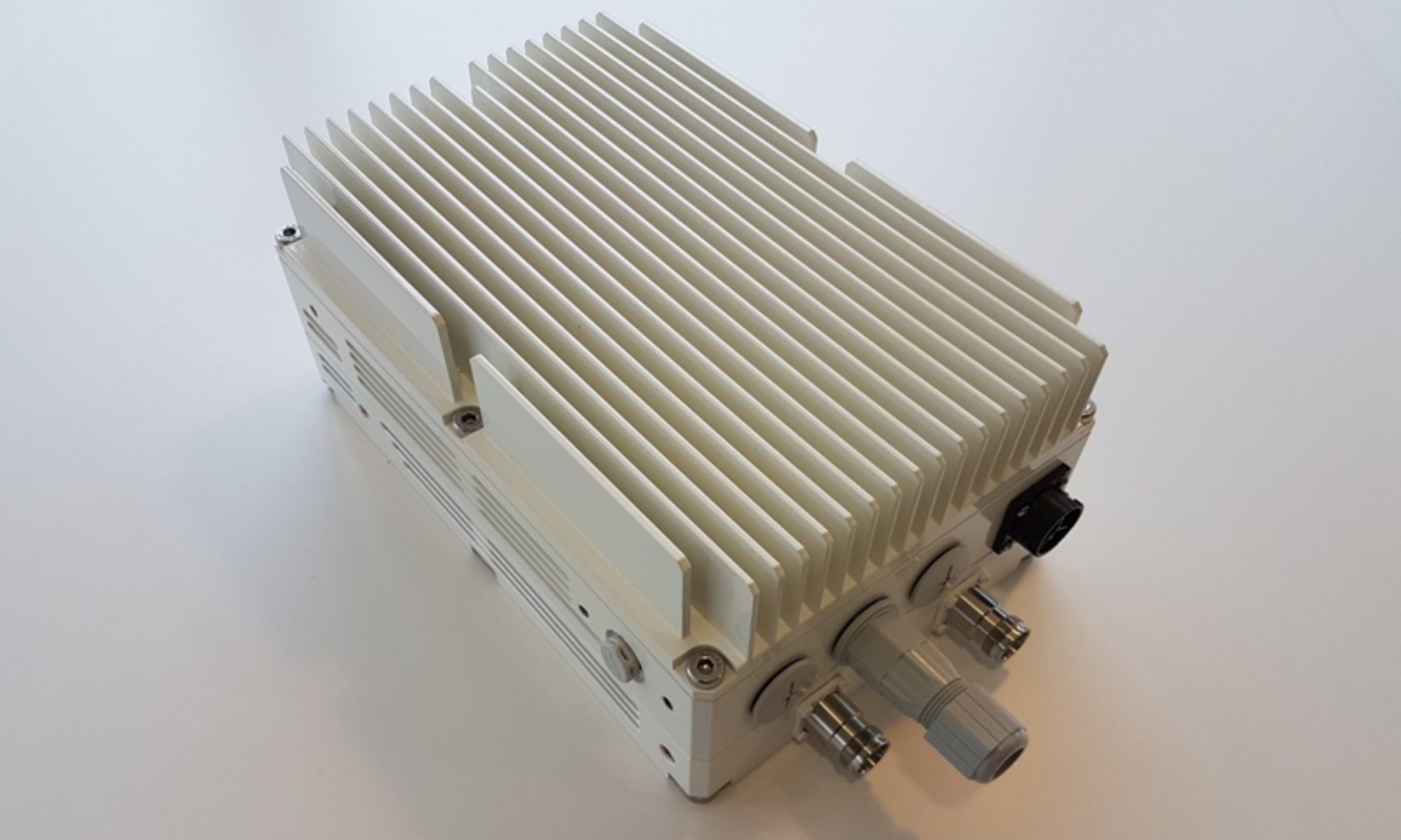
CableFree Remote Radio Head (RRH) used for 5G-SA and 5G-NSA networks
Standalone 5G-NR comprises a new end-to-end architecture that uses mm-Waves and sub-GHz frequencies and this mode will not make use of the existing 4G LTE infrastructure. The SA 5G NR will use enhanced mobile broadband (eMBB), Ultra-Reliable and Low Latency Communications (URLLC), and huge machine-type communications (mMTC) to implement multi-gigabit data rates with improved efficiency and lower costs.
5G SA also enables more advanced network slicing capabilities, helping operators rapidly transition to both 5G New Radio (NR) and 5G as the core network. Network slicing, URLLC, and mMTC bring ultra-low latency along with a wide range of next-gen use cases like remote control of critical infrastructure, self-driving vehicles, advanced healthcare, and more. However, the NR advanced cases are not backward compatible with the EPC, which is the framework that provides converged voice and data on a 4G LTE network. The level of reliability and latency that 5G provides will be indispensable for handling smart-grid control machines, industrial automation, robotics, and drone control and coordination.
5G-NSA Architecture
NSA-5G NR is considered as the early version of SA 5G NR mode, in which 5G networks are supported by existing LTE infrastructure. It fundamentally concentrates on eMBB, where 5G-supported handsets and devices will make use of mmWave frequencies for increased data capacity but will continue to use existing 4G infrastructure for voice communications.
NSA helps MNOs launch 5G quickly for eMBB to get a competitive edge in the telecom market. NSA also helps leverage its existing LTE/VoLTE footprint to maximize the LTE installed base and boost capacity while increasing delivery efficiency. It will not support network slicing, URLLC, and mMTC, but its higher broadband speeds will enable services such as video streaming, augmented reality (AR), virtual reality (VR), and an immersive media experience.
Non-Standalone 5G NR will provide increased data-bandwidth by using the following two new radio frequency ranges:
Frequency range 1 (450 MHz to 6000 MHz) – overlaps with 4G LTE frequencies and is termed as sub-6 GHz. The bands are numbered from 1 to 255.
Frequency range 2 (24 GHz to 52 GHz) – is the main mmWave frequency band. The bands are numbered from 257 to 511.
Technical Differences between 5G SA and 5G NSA
The main difference between NSA and SA is that NSA provides control signaling of 5G to the 4G base station, whereas in SA the 5G base station is directly connected to the 5G core network and the control signaling does not depend on the 4G network. In simple terms, NSA is like adding a solid-state drive to an old computer, which can improve the system’s performance, while SA is like replacing it with a new computer that has newer technologies and optimum performance.
Some benefits include:
5G-NSA is a low-cost update of core compared to a 5G Core needed for 5G-SA.
5G-NSA eases 5G network deployments as it reuses existing 4G facilities, thus allowing rapid time to market for 5G mobile broadband.
With NSA, the deployment is faster and time-to-market is lower, as 4G locations can be used to install 5G radio. SA requires building 5G base stations and the back-end 5G core network to fully realize the characteristics and functions of 5G.
SA involves a 5G core with SBA for scalability and flexibility to deliver a superfast network with ultra-low latency for advanced 5G use cases.
5G Usage Scenarios in NSA and SA Operation
The requirements of 5G NR for the SA provide a complete set of specifications for the 5G core network that goes beyond NSA. The three major usage scenarios defined for 5G by the 3GPP and GSMA include:
Enhanced mobile broadband (eMBB)
Ultra-reliable and low latency communications (URLLC)
Massive machine-type communications (mMTC)
Future 5G Networks Include both NSA and SA
Early adopters of 5G primarily focus on 5G-NSA deployments as they compete to deliver 5G speeds with a quick time to market. These MNOs can move to SA-based architecture over a period of time, which most plan to do. 5G-NSA deployment remains a mainstream solution given its ability to handle both 4G- and 5G-based traffic, keeping these early adopters ahead of their competition as they undertake their network transformation. 5G devices are not widespread so the need for 5G-SA-based architecture is still nascent.
For the future, the convergence of NSA and SA will help operators move to a full 5G network. A complete virtualized 5G architecture will allow MNOs to migrate and choose varied functionalities of their existing NSA solution to the 5GC platform, as new 5G services are launched, allowing them to monetize their investment gradually rather than move all at once and enabling them to recover their costs over time.
Although 5G-SA is a more mature network architecture compared to 5G-NSA, NSA will continue to be the more commonly chosen path to 5G. All NSA single-mode 5G phones launched this year or early next year will be valid for a decade, and as SA architecture permeates, more and more 5G-SA devices will be in our homes and businesses.
Explaining 5G NR PRACH function, contents and mapping
PRACH is used to carry random access preamble from UE towards gNB (i.e. 5G NR base station). • It helps gNB to adjust uplink timings of the UE in addition to other parameters. • Zadoff chu sequences are used to generate 5G NR random access preamble similar to LTE technology. • Unlike LTE, 5G NR random access preamble supports two different sequence lengths with various format configurations as shown in the figure. The different formats help in wide deployment scenarios.
Random Access Preamble
A: Long sequence of length 839 B: Short sequence of length 139 s: Zadoff chu sequence
Long Sequence
The 839 long sequence uses four preamble formats like LTE. These formats are designed for large cell deployment in FR1 (Sub-6 GHz range). They use subcarrier spacing of 1.25 KHz or 5 KHz.
Short Sequence
The 139 short sequence uses nine preamble formats. These formats are designed for small cell deployment including indoor coverage. These preamble formats are used for both FR1 (sub-6 GHz) and FR2 (mmwave) ranges. In FR1, it supports 15 or 30 KHz where as in FR2, it supports 60 or 120 KHz. subcarrier spacing.
5G NR PRACH physical layer processing
• PRACH uses same FFT as used for data. • OFDM baseband signal generation for PRACH is defined in 3GPP TS 38.211 section 5.3.2. • Engineers often come across situations (test cases) in which UE does not receive response from gNB for the PRACH message transmitted by it. During such scenarios, they need to analyze the test case with respect to various layers such as radio link, physical layer (L1) and last upper layer messages. This helps them diagnose the radio network issues and find root cause of any problems reported.
5G NR Terminologies – 5G Subcarrier Spacing, 5G Frame & Subframe, Slot and Symbol
Explaining 5G Subcarrier spacing as compare to LTE, 5G Frame and Subframe, possibilities of different type of 5G NR slot depending upon the different subcarrier spacing and OFDM symbol:
5G Subcarrier Spacing
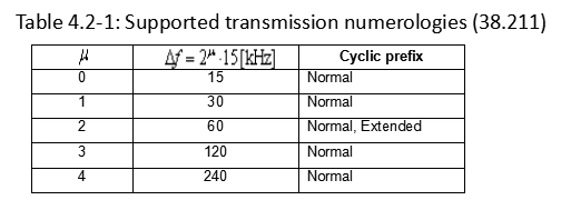
In 5G NR, subcarrier spacing of 15, 30, 60, 120 and 240 KHz are supported.
As you see here, each numerology is labled as a parameter (u, mu in Greek). The numerology (u = 0) represents subcarrier spacing of 15 kHz which is same as LTE. And as you see in the second column the subcarrier spacing other than 15KHz, for 5G NR.
NOTE: In LTE, there is only type of subcarrier spacing (15 KHz), whereas in NR, multiple types of subcarrier spacing are available.
5G Frame and Subframe
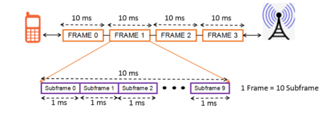
Downlink and uplink transmissions are organized into frames with 10ms duration, each consisting of ten subframes of 1ms
Each frame is divided into two equally-sized half-frames of five subframes each with half-frame 0 consisting of subframes 0 – 4 and half-frame 1 consisting of subframes 5 – 9.
In Total, there are 10 subframes in one frame.
5G Slot
Slot length gets different depending on different subcarrier spacing. The general tendency is that slot length gets shorter as subcarrier spacing gets wider. Actually this tendency comes from the nature of OFDM.
Number of slots per subframe varies with carrier spacing
There can be 1, 2, 4, 8, or 16 slots per subframe
NOTE: In LTE, there are fixed two slots per subframe, but in NR, no. of slot may vary.
5G OFDM symbol
The number of symbols within a slot does not change with the numerology or subcarrier spacing.
OFDM symbols in a slot can be classified as ‘downlink’ (denoted ‘D’), ‘flexible’ (denoted ‘X’), or ‘uplink’ (denoted ‘U’).
In a slot in a downlink frame, the UE shall assume that downlink transmissions only occur in ‘downlink’ or ‘flexible’ symbols.
In a slot in an uplink frame, the UE shall only transmit in ‘uplink’ or ‘flexible’ symbols.
The number of symbols per slot is 14 (in case of Normal CP)
The number of symbols per slot is 12 (in case of Extended CP)
NOTE: In NR slot format, DL and UL assignment changes at a symbol level (in LTE TDD the UL/DL assignment is done in a subframe level)
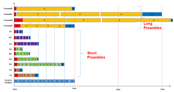
Understanding 5G-NR RACH Preamble Types: Long and Short Preambles
A preamble is send by UE to gNB over PRACH channel to obtain the UL synchronization. Similar to LTE, in 5G NR there are 64 preambles defined in each time-frequency PRACH occasion. The preamble consists of two parts cyclic prefix (CP) and Preamble Sequence.
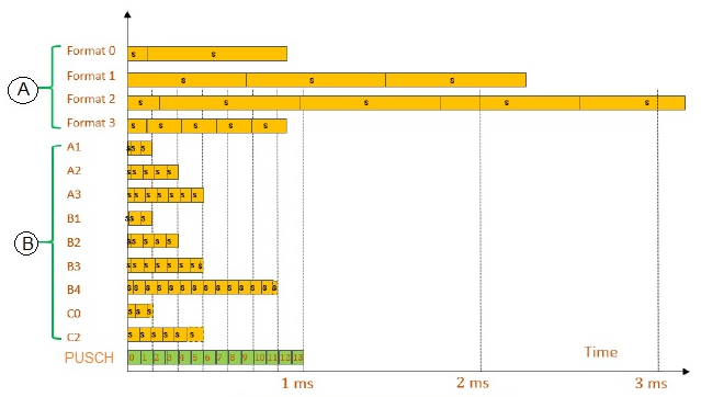
In 5G NR, there are 13 types of preamble format supported known as Format 0, Format 1, Format 2,Format 3,Format A1,Format A2,Format A3,Format B1, Format B2, Format B3, Format B4, Format C0, Format C1. These 13 types of preamble format can be grouped into two categories:
Long Preamble
Short Preamble
Differences in the time domain of different preamble formats includes different CP length, Sequence Length, GP length and number of repetitions can be seen in below picture.
Long Preamble Characteristics
Long preambles are based on a sequence length L=839
Sub-carrier spacing for long preambles can be either 1.25 Khz or 5 Khz
Numerology used for long preambles is different from any other NR transmissions
Origin of long preambles partly from the preambles used for LTE
Long preambles can only be used for FR1 frequency bands which is below 6 Ghz
There are four different formats for the long preamble name Format#0, Format#1, Format#2 and Format#3
The preamble format is part of the cell random-access configuration and each cell is limited to a single preamble format
NR preamble format 0 and 1 are identical to the LTE preamble formats 0 and 2
A long preamble with 1.25 kHz numerology occupies six resource blocks in the frequency domain, while a preamble with 5 kHz numerology occupies 24 resource blocks
Short Preamble Characteristics
Short preambles are based on a sequence length L=139
The sub-carrier spacing for short preambles is aligned with the normal NR sub-carrier spacing i.e. 15Khz, 30Khz, 60Khz and 120Khz.
Short preambles use a sub-carrier spacing of:
15 Khz or 30 Khz in the case of operation below 6 Ghz (FR1)
60 Khz or 120 Khz in the case of operation in the higher NR frequency bands (FR2).
A short preamble occupies 12 resource blocks in the frequency domain regardless of the preamble numerology
The short preambles are, in general shorter than the long preambles and often span only a few OFDM symbols
Short preambles formats are designed such that the last part of each OFDM symbol acts as a CP for the next OFDM symbol and the length of a preamble OFDM symbol equals the length of data OFDM symbols
In most cases it is therefore possible to have multiple preamble transmissions multiplexed in time within a single RACH slot (occasion). In other words, for short preambles there can may be multiple RACH occasions in the frequency domain as well as in the time domain within a single RACH slot .
5G NR supports mix of the “A” and “B” formats to enable additional formats like A1/B1, A2/B2, and A3/B3.
Short preamble formats A and B are identical except for a somewhat shorter cyclic prefix for the B formats.
Preamble formats B2 and B3 are always used in combination with the corresponding A formats (A2 and A3)
Short preambles are design to targeting the small/normal cell and indoor deployment scenarios
Short preambles allows the gNB receiver to use the same fast Fourier transform (FFT) for data and random-access preamble detection.
These preambles are composition of multiple shorter OFDM symbols per PRACH preamble,makes them more robust against time varying channels and frequency errors.
Short preambles supports analog beam sweeping during PRACH reception such that the same preamble can be received with different beams at the gNB
Spectral efficiency is an important consideration for 5G-NR radios, as it was for 4G/LTE: The amount of information that fits in a given channel bandwidth or one just say how efficiently can that piece of spectrum be used to transmit information.
There is a hard limit to how much data can be transmitted in a given bandwidth – this limit is well-known as the Shannon-Hartley Theorem and commonly referred to as the Shannon limit.
Spectral efficiency is usually expressed as “bits per second per hertz,” or bits/s/Hz, defined as the net data rate in bits per second (bps) divided by the bandwidth in hertz. Net data rate and symbol rate are related to the raw data rate which includes the usable payload and all overhead.
raw data rate = Payload + Overhead
net data rate = raw data rate – overhead
Spectral efficiency = net data rate in bps / Channel Bandwidth in Hz
For example, a system uses channel bandwidth as 2 MHz and it can support a raw data rate of say 15 Mbps, assuming 2 Mbps as overhead then net date rate will be as 13 Mpbs, then its spectrum efficient can be calculated as follows:
Spectral efficiency= 13 x 10^6 / 2 x 10^6 = 6.5 bits/second/Hz
Calculating Spectral Efficiency for LTE:
An LTE system can support a maximum channel bandwidth as 20 MHz (Not including Carrier Aggregation). Its symbol rate can be calculated as
Symbols/Second = 1200 x 14 x 1000 = 16,800,000 Symbols/Second
Considering 64-QAM as highest modulation for downlink each symbol can carries 6 bits provide raw data rate as follows:
raw data rate = 16,800,000 x 6 = 100.8 Mbps (No MIMO considered)
Consider 4×4 MIMO: theoretically it makes raw data rates four times i.e. 400 Mbps. assuming 25 % as overhead the net data rate will be as 300 Mbps. Similarly data rate can be calculated for uplink . In a 1×1 LTE uplink there is no MIMO, so Max raw data can be 100 Mbps with 64-QAM support in Uplink and after deducted 25% overhead net data rate for uplink will be 75 Mbps. Uplink net date with 16-QAM will be 51 Mbps.
Downlink Spectral Efficiency = 300 x 10^6 bps / 20 x 10^6 Hz = 15 bits/second/Hz
5G New Radio is capable of providing a downlink throughput 2.31 Gbps and uplink throughput of 2.47 Gbps with certain configuration shown below assuming 100 MHz channel bandwidth. (Single carrier component)
Downlink Spectral Efficiency = 2.31 x 10^9 bps / 100 x 10^6 Hz = 23 bits/second/Hz
Uplink Spectral Efficiency = 2.47 x 10^9 bps / 100 x 10^6 Hz = 24 bits /second / Hz
Note: The values shown here are just theoretical value considering sensible baseline assumptions. Real-world network performance may differ.
For Further Information
For more information on Spectral Efficiency of 5G-NR radios,
What is the RAN Intelligent Controller (RIC) used in Open RAN (ORAN) Networks?
History: from 2G to now
From the era of 2G and 3G, mobile architectures had specific controllers that were responsible for RAN orchestration and management. Then from 4G, overall network architecture became flatter and the expectation was that, to enable optimal subscriber experience, base stations would use the X2 interface to communicate with each other to handle resource allocation. This scenario created the proverbial vendor lock-in as different RAN vendors had their own flavor of X2, and it became difficult for an Operator/MNO to have more than one RAN vendor in a particular location. The O-RAN Alliance went back to the controller concept to enable best-of-breed Open RAN.
Open RAN Intelligent Controller (RIC) used in modern wireless networks
Why is RIC needed?
As many 5G experiences require low latency, 5G specifications like Control and User Plane Separation (CUPS), functional RAN splits and network slicing, require advanced RAN virtualization combined with SDN. This combination of virtualization (NFV and containers) and SDN is necessary to enable configuration, optimization and control of the RAN infrastructure at the edge before any aggregation points. This is how the RAN Intelligent Controller (RIC) for Open RAN was born – to enable eNB/gNB functionalities as X-Apps on northbound interfaces. Applications like mobility management, admission control, and interference management are available as apps on the controller, which enforces network policies via a southbound interface toward the radios. RIC provides advanced control functionality, which delivers increased efficiency and better radio resource management. These control functionalities leverage analytics and data-driven approaches including advanced ML/AI tools to improve resource management capabilities.
The separation of functionalities on southbound and northbound interfaces enables more efficient and cost-effective radio resource management for real-time and non-real-time functionalities as the RIC customizes network optimization for each network environment and use case.
Virtualization (NVF or containers) creates software app infrastructure and a cloud-native environment for RIC, and SDN enables those apps to orchestrate and manage networks to deliver network automation for ease of deployment.
Though originally RIC was defined for 5G OpenRAN only, the industry realizes that for network modernization scenarios with Open RAN, RIC needs to support 2G 3G 4G Open RAN in addition to 5G.
Source: O-RAN Alliance
Working group 1 looks after overall use cases and architecture across not only the architecture itself, but across all of the working groups.
Working group 2 is responsible for the Non-real-time RAN Intelligent Controller and A1 interface, with the primary goal that Non-RT RIC is to support non-real-time intelligent radio resource management, higher layer procedure optimization, policy optimization in RAN, and providing AI/ML models to near-RT RIC.
Working group 3 is responsible for the Near-real-time RIC and E2 interfaces, with the focus to define an architecture based on Near-Real-Time Radio Intelligent Controller (RIC), which enables near-real-time control and optimization of RAN elements and resources via fine-grained data collection and actions over the E2 interface.
Working group 5 defines the Open F1/W1/E1/X2/Xn interfaces to provide fully operable, multi-vendor profile specifications that are compliant with 3GPP specifications.
The RAN Intelligent Controller consists of a Non-Real-time Controller (supporting tasks that require > 1s latency) and a Near-Real Time controller (latency of <1s). Non-RT functions include service and policy management, RAN analytics and model-training for the Near-RT RAN.
A Near Real-Time RAN Intelligent Controller (Near-RT RIC) is a near‐real‐time, micro‐service‐based software platform for hosting micro-service-based applications called xApps. They run on the near-RT RIC platform. The near-RT RIC software platform provides xApps cloud-based infrastructure for controlling a distributed collection of RAN infrastructure (eNB, gNB, CU, DU) in an area via the O-RAN Alliance’s E2 protocol (“southbound”). As part of this software infrastructure, it also provides “northbound” interfaces for operators: the A1 and O1 interfaces to the Non-RT RIC for the management and optimization of the RAN. The self-optimization is responsible for necessary optimization-related tasks across different RANs, utilizing available RAN data from all RAN types (macros, Massive MIMO, small cells). This improves user experience and increases network resource utilization, key for consistent experience on data-intensive 5G networks.
Source: O-RAN Alliance
The Near-RT RIC leverages embedded intelligence and is responsible for per-UE controlled load-balancing, RB management, interference detection and mitigation. This provides QoS management, connectivity management and seamless handover control. Deployed as a VNF, a set of VMs, or CNF, it becomes a scalable platform to on-board third-party control applications. It leverages a Radio-Network Information Base (R-NIB) database which captures the near real-time state of the underlying network and feeds RAN data to train the AI/ML models, which are then fed to the Near-RT RIC to facilitate radio resource management for subscriber. Near-RT RIC interacts with Non-RT RIC via the A1 interface to receive the trained models and execute them to improve the network conditions.
The Near-RT RIC can be deployed in a centralized of distributed model, depending on network topology.
Source: O-RAN Alliance
RIC Summary
The RIC platform provides a set of functions via xApps and using predefined interfaces that allow for increased optimizations in Near-RT RIC through policy-driven, closed loop automation, which leads to faster and more flexible service deployments and programmability within the RAN. It also helps strengthen a multi-vendor open ecosystem of interoperable components for a disaggregated and truly open RAN.
Estimating the Maximum Throughput and 5G Capacity for modern Wireless Networks is complex and requires understanding of the 5G standards. This page is aimed at summarising what’s involved:
5G Maximum Capacity Estimation
Throughput estimation for 5G is complex, involving many factors and deep knowledge of the 5G standards. However, the rough estimation for a maximum throughput can roughly be estimated by following equation:
From:
< 38.306 – 4.1.2 Max data rate without ue-CategoryDL and ue-CategoryUL >
5G Capacity:
The meaning of each parameter in this equation is as follows:
5G Capacity Formula
Explaining the formula in more detail:
For 5G NR, the approximate data rate for given number of aggregated carriers in a band or band combination is calculated using the above equation or formula. The following fields are used in 5G NR throughput calculation:
➤J : number of aggregated component carriers in a band or band combination ➤Rmax : 948/1024 • For the j-th CC, Vlayers(j) is the maximum number of layers ➤Qm(j) : Maximum modulation order, Qm is 2 for QPSK, 4 for 16QAM, 6 for 32QAM, 8 for 256QAM ➤f(j) : Scaling factor, can take any value from 1/0.8/0.75/0.4 ➤μ : 5G NR Numerology, can take any value from 0 to 5. ➤Tsμ : Average OFDM symbol duration in a subframe for μ value, • Tsμ = 10-3/(14*2μ). ➤NPRBBW(j),μ : Maximum RB Allocation in bandwidth, BW(j)with numerology (μ), BW(j) is UE supported maximum Bandwidth in given band or in band combinations. REs are grouped into PRBs (Physical Resource Blocks). Each PRB consists of 12 Subcarriers. ➤OH(j) : Overhead which takes any of the following values. • [0.14] → Frequency Range FR1 for DL • [0.18] → Frequency Range FR2 for DL • [0.08] → Frequency Range FR1 for UL • [0.10] → Frequency Range FR2 for DL
Above mentioned formula has been used along with 5G NR Physical layer parameters and other 5G NR system parameters in order to develop 5G NR throughput calculator. One can refer following pdf which covers snapshot of 3GPP TS 38.306 document for more information on 5G NR data rate calculation. The maximum transmission bandwidth configuration NRB for each UE channel bandwidth and subcarrier spacing are specified in the tables below.
3GPP References
• 3GPP TS 38.306 V15.2.0 (2018-06)
Maximum 5G Throughput & Capacity Calculators
We noted a few of examples of the maximum throughput calculators on the Internet as listed below. Disclaimer: these are what we found on the Internet – results may vary and accuracy is not known or warranted.
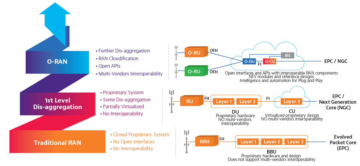
An Open Radio Access Network (O-RAN) is a disaggregated approach to deploying mobile fronthaul and midhaul networks built entirely on cloud native principles. O-RAN underscores streamlined 5G RAN performance objectives through the common attributes of efficiency, intelligence and versatility. Open RAN deployed at the network edge will benefit 5G applications such as autonomous vehicles and the IoT, support network slicing use cases effectively, and enable secure and efficient over-the-air firmware upgrades.
O-RAN is an evolution of the Next Generation RAN (NG-RAN) architecture, first introduced by the GSMA’s 3GPP in their release 15 (5G version 1) technical specification TS 38.401. The O-RAN Alliance formed to undertake the advancement of NG-RAN philosophies, expanding on the scope of what was originally outlined by the 3GPP. Comprising over 1601 member companies, the O-RAN alliance issues specifications and releases open source software under the auspices of the Linux Foundation.
TS 38.401 decomposed the existing Baseband Unit (BBU) into two functional components, a Distributed Unit (DU) and Central Unit (CU). Conforming to modern control user plane separation (CUPS) constructs, the Central Unit can be further decoupled into distinct control plane (CU-CP) and user plane (CU-UP) functions. Replacing the monolithic BBU with the CU/DU allows for new deployment models which feature centralized packet processing functions, while laying the groundwork for separating baseband functions from the (remote) radio unit (RRU/RU).
ORAN explained: Picture courtesy VIAVI solutions
O-Ran Benefits
Operational efficiencies have been realized through past RAN innovations such as cloud RAN (cRAN), but previous advancements did not free operators from vendor lock-in. By enabling an open, multi-vendor RAN ecosystem, O-RAN introduces cloud-scale economies and competition to the RAN. Marketplace factors, combined with a more elastic and flexible RAN architecture that is already taking shape through virtualization, can enable much faster time to market (TTM) than was previously possible.
Moving away from the vendor-specific RAN paradigm not only enables more flexibility for operators, it also minimizes the “secret sauce” that leaves them reliant on a single vendor for all aspects of RAN implementation and optimization.
Competition and proliferation resulting from of new entrants can potentially drive down O-RAN equipment costs. The inter-carrier, interoperability aspects of Open RAN can also be used to increase efficiencies for existing LTE networks as they continue to incorporate the virtualization and disaggregation that are prerequisite 5G RAN deployment.
A CableFree Remote Radio Head (RRH) used for O-RAN networks
This affords numerous technical and operational advantages, regardless of whether the RRU, DU and CU remain co-located within a 5GNodeB (gNB), like existing NodeB RRU/BBU implementations, or the CU is physically deployed to a more centralized location. The centralization of the CU in an aggregation site reduces costs and accelerates the implementation of dynamic and highly automated multiaccess edge compute (MEC) clouds for the RAN (aka C-RAN). This functional decoupling will also enable the adoption of modern transport protocols which can also align with the 5G core user plane (i.e. SRv6) while easing the addition of new latency, high-bandwidth, AI/ML-driven applications.
The deployment of NG-RAN components is defined as being with or between the fronthaul, midhaul and backbone network. Open interfaces are described as either lower-layer splits (LLS), in the case of the RU to DU connection, or higher-layer splits (HLS) as with the link between the DU and CU. This nomenclature is descriptive of the OSI layer (i.e. L1/L2/L3) exposed by the interface and handled by the NG-RAN function. Where components are instantiated will depend on the requirements of the service slice. A low latency service might demand a CU be co-located with the DU in the access layer while a slice supporting a simple machine to machine communications application would scale more cost effectively with a CU within the network core.
NG-RAN clearly defines the DU and CU plus the F1, E1, Xn and NG between them and the core network but stops short of outlining the service management framework and interfaces required for the RAN to operate within an orchestrated and automated cloud environment. TS 38.401 also fails to address the RU-DU interface. Without further definition, it would be logical to adopt the exiting Common Public Radio Interface (CPRI) defined between the RRU-BBU. Although theoretically a standard, this interface has been heavily modified by individual vendors, effectively locking their RRU to their BBU.
While CPRI is a high-speed serial interface, the bandwidth demands of 5G will stretch the limits of local fiber and increase the need for more radio units. Current implementations do not allow for the DU to reduce this burden by offloading some of its functionality to the RU. While the enhanced CPRI (eCPRI) interface was originally proposed as an alternative, this specification was also developed by just four2 large vendors. The O-RAN Alliance has therefore taking on the task of defining new Open Fronthaul user and management plane interfaces between the DU and RU.
To ensure openness, O-RAN decouples hardware and software into 3 layers: The commercial off the shelf (COTS) merchant silicon (including x86), a hardware abstraction layer and an application layer, where the RAN functions reside. Ensuring each layer is vendor agnostic, the O-RAN alliance has specified a list of requirements for a cloud platform which supports the execution of O-RAN network functions. This is referred to as the O-RAN Cloud Platform, or O-Cloud. Deploying O-RAN functions on x86 hardware in cloud native environments using lightweight (OS virtualization) containers demands a strong emphasis on data plane acceleration. This must be achieved at the application level, as these functions will not have access to the Kernel. As such, solutions may be specific to each O-RAN CNF but leverage standard techniques such as DPDK and FD.io or employ more advanced techniques.
O-RAN challenges
Creating seamless interoperability in a multi-vendor, open ecosystem introduces new test, management and integration challenges that require diligence and cooperation to overcome. In the single-vendor model, accountability is a foregone conclusion and problem isolation and troubleshooting are managed through an established command structure.
Dispersion of vendors could potentially lead to finger pointing when root cause identification is inconclusive. These same complications could plague on-time launch schedules and revenue growth by diluting management and orchestration responsibilities across an array of new O-RAN players.
The enticing Open RAN concept of flexible interoperability also brings challenges for test and integration. To fulfill the O-RAN promise of reduced OPEX and total cost of ownership (TCO), operators must take responsibility for multi-vendor, disaggregated elements and make sure they perform together to maintain QoE standards.
With Open RAN reducing the barrier to entry for dozens of new players, interoperability is a paramount concern for both the O-RAN ALLIANCE and OpenRAN group. An Open Test and Integration Center (OTIC) has been established as a collaborative hub for commercial Open RAN development and interoperability testing. The operator led initiative benefits from the support of global telecom organizations with a shared commitment to verification, integration testing, and validation of disaggregated RAN components.
Summary
Traditional RAN designs and architectures will still persist in being used. Some operators will prefer Open RAN designs and architecture. Many operators will allow for both options in their network evolution and planning.
Why consider Shared Spectrum for Private 5G and 4G LTE networks?
Shared spectrum solutions for 4G and 5G enable the use of the same spectrum range in a single geographic area by more than one organisation. This is different than Unlicensed Spectrum which is uncontrolled and generally suffers interference. Shared Spectrum is licensed and therefore Private 5G can operate in deterministic manner.
Here is a snapshot for 2020: recent examples of spectrum initiatives to private mobile networking are outlined (nonexhaustive list).
Countries with identified private network deployments (4G & 5G)
Which countries are planning Shared Spectrum?
Australia: In August 2020, ACMA launched a consultation on plans for area-wide apparatus licences for wireless broadband in the 24.7–27.5 GHz frequency range of the 26 GHz band; wireless broadband and FSS in the 27.5–29.5 GHz range; and FSS in the 29.5–30 GHz range. It is envisaged these licences would support private network and local WISP use-cases. ACMA is planning to make the spectrum at 24.7–25.1 GHz and 27.5–29.5 GHz available Australia-wide via an administrative process, with applications opening in October 2020 and licences available from December 2020. Licences for spectrum from 25.1 GHz to 27.5 GHz would be available via administrative process only after the conclusion of an auction of spectrum in this range covering key metropolitan and regional areas scheduled for Q1 2021. That administrative process is scheduled to begin in May 2021 with licences issued by the end of June 2021.
Belgium: In December 2019 BIPT launched a consultation on a draft bill and three draft royal decrees concerning among other things, the possibility of authorising local private networks using 4G or 5G in the 3800–4200 MHz band.
Brazil: An auction is expected in H1 2021 covering various bands with spectrum set aside for private networks: 2390–2400 MHz, 3700–3800 MHz, 27.5–27.9 GHz.
Chile: In November 2019 Chile passed a resolution designating spectrum from 3750 MHz to 3800 MHz for private 5G networks.
Croatia: Croatia is planning an auction of multiple spectrum bands. Due to the impact of COVID-19, the auction has been delayed from 2020 to H1 2021. It intends to auction at least 300 MHz in the 3410–3800 MHz range on a national basis, with remaining 90 MHz of spectrum potentially available for local or private networks.
Finland: Spectrum at 24.25–25.1 GHz is being reserved for the construction of local, private networks in the future.
France: At the end of March 2019, applications were closed for requests to run 5G trials at 26 GHz. The French regulator ARCEP accepted 11 schemes backed by public and private network operators. The various private network projects include inter alia deployment of a 5G network at the National Vélodrome in Saint-Quentin-enYvelines, a network at Lyon Part-Dieu station offering both public and private 5G services (the latter to enable station management and train telematics) and a network at The Grand Maritime Port of Le Havre for smart grid and logistics applications. In May 2019, ARCEP opened up the possibility of wider private use of TDD spectrum at 2.6 GHz (2575–2615 MHz) for very-high-speed mobile networks (Air France KLM has already been trialling private LTE in this band for a number of years). Then in September, after a public consultation, it confirmed that it would be allocating the spectrum on a regional basis in order to improve broadband coverage for enterprises. Enterprises must express interest in using the spectrum, which will either be allocated (in the case of no competition for the spectrum) or ARCEP will determine a (possibly competitive) system of allocation. So far three applications have been accepted. ARCEP has also opened the possibility of private network deployment in C-Band spectrum. In order to ensure organisations can get access to mobile services with sufficient coverage and performance, the terms of the licences for C-Band spectrum awarded in September 2020 included commitments to respond to reasonable requests from enterprise and public sector organisations for the supply of services, either through the supply of services on its own network or through sub-licensing of the frequency on a geographically limited basis.
Germany: In November 2019 Germany’s regulator, Bundesnetzagentur, opened up applications for use of the 3700–3800 MHz band for local and regional 5G networks. Stating that it wants Germany to be a pioneer in Industry 4.0, in addition to industrial users, the regulator anticipates the spectrum being leased by organisations in the agricultural and forestry sectors. Frequencies can be used immediately after allocation. The right to apply for spectrum derives from ownership or from another legal right to use the associated land, and fees are related to size of the geographic area covered by the licence, the amount of spectrum allocated and the duration.
The regulator has also been preparing a framework for the assignment of spectrum at 24.25–27.5 GHz for local applications. After consultation it is proposed the entire range be assigned on a technology and service neutral basis (starting with spectrum from 26.5-27.5 GHz). The new plans were opened up to a consultation which ended in August 2020. No limit is proposed for the geographical size of a local frequency assignment, although the licensee must have a plan for service availability throughout that area within a year. The results have not yet been published.
Hong Kong: In July 2019, the regulator OFCA announced that it would be making 400 MHz in the 27.95–28.35 GHz range available for Localised Wireless Broadband Licences (using 5G or other advanced mobile technologies) on a geographic-sharing basis. It opened up applications for assignment of the shared spectrum later the same month. GSA is aware of one active licence. OFCA has also stated plans to assign spectrum at 617–698 MHz and 703–803 MHz for indoor mobile services, with the spectrum available from 2021 at the earliest.
Japan: In December 2019, the Ministry of Internal Affairs and Communications began accepting applications for local 5G licences. The spectrum available spans 28.2–28.3 GHz and can be used within the applicant’s own building or on its own land to provide broadband fixed wireless services. National carriers are not eligible to apply, as the spectrum is not intended to supplement national carriers’ existing holdings. MIC also stated it would consider allocation of spectrum at 4.6–4.9 GHz and 28.2–29.1 GHz for local private services in the future. (In 2017, Japan also made the 1.9 GHz band, Band 39, previously used for PHS and DECT available for private LTE networks as a shared band.)
Malaysia: In January 2020, the MCMC stated that spectrum at 26–28 GHz will be assigned in two parts. Spectrum at 24.9–26.5 GHz will be tendered (beauty contest) to licensees on a national basis. Spectrum at 26.5–28.1 GHz will be assigned on a first-come, first-served basis for the deployment of local/private networks ‘for industrial and enterprise services and applications for, but not limited to, healthcare, ports, transportation, manufacturing, agriculture, public safety and smart city projects’. Proceedings have been delayed, however.
Netherlands: Spectrum at 3.5 GHz is already widely used for local and private network applications, although the government is reorganising the spectrum. It intends to make spectrum at 3500–3700 MHz available nationally from September 2022. Spectrum at 3400–3450 MHz and 3750–3800 MHz is then intended to be made available for local use from 2026. Spectrum at 3450–3500 MHz and 3700–3750 MHz is already used and currently protected for national security reasons. Netherlands’ Digital Connectivity Action Plan foresees the use of spectrum at 26 GHz either for a very large number of local permits or for shared use.
New Zealand: Spectrum at 2.5 GHz (2575–2620 MHz) is available in New Zealand for local or regional Managed Spectrum Park (private) licences (often for regional wireless broadband services). Eighty licences were awarded in 2009 after an initial round of applications. Subsequent licences have been made available on a first-come, first-served basis, with a number of licences awarded during 2019. Licences last for six years. There are limits on geographic coverage of licences held by any single organisation.
Norway: The Norwegian regulator Nkom is considering a joint assignment of various spectrum bands in 2021, two of which – the 2300–2400 MHz band and 3600 MHz – are under consideration for use for allocation to local/regional permits. In June 2020, it launched a consultation on plans to offer local/regional permits at 2300 GHz and 26 GHz.
Poland: In April 2019, Poland launched a consultation about the amount of spectrum to be made available at 3400–3800 MHz, with two options: a) 200 MHz in four lots of 50 MHz or b) 400 MHz (four national lots of 80 MHz plus 80 MHz for local use). In December, it announced a new consultation on the details of an auction of four lots at 80 MHz. Local use details had not been released at the time of writing.
Russia: In December 2019, Russia’s Deputy Minister of Digital Development, Telecommunications and Mass Communications stated that the government was preparing an auction of mmWave spectrum at 25.25–27.5 GHz (with six lots, four federal lots of 400 MHz and two regional lots of 250 and 400 MHz). Then in March 2020, SRCF published its decision that it would open up spectrum use at 24.25–24.65 GHz for an unlimited number of users for the purposes of creating private networks. Russia SRFC is also reportedly planning to allocate chunks of spectrum at 400 MHz for private LTE networks.
Slovenia: In August 2020, Slovenia announced draft terms and conditions on plans for a multi-band spectrum covering various bands. A portion of the spectrum at 2300 MHz (2300–2320 MHz and 2390–2400 MHz) and at 3600 MHz (3400–3420 MHz) is expected to be set aside for local use (including for private use). The latest timetable envisages the completion of the auction before the end of 2020.
Sweden: PTS intends to enable local permits for the use of spectrum in the 3720–3800 MHz range. These will be awarded and managed through an administrative process. PTS initiated consultations on the demand for 5G frequencies in the 24.25–27.5 GHz bands and in December 2019, stated that it intended – as soon as possible – to allocate parts of the spectrum range for both local and large-scale 5G use. In its consultation, launched in April 2020, it proposed before the end of 2021 authorising the use of spectrum at 24.25–25.1 GHz for local 5G services, with licences valid to end 2025 and limited to indoor use.
UK: Following consultations, in July 2019, Ofcom announced plans to initiate spectrum sharing with localised licensing of key spectrum bands. Its aim is to open up use of the spectrum to private network operators such as enterprises and utilities. The spectrum that will be available through local licences includes: • 3800–4200 MHz • 1781.7–1785 MHz/1876.7–1880 MHz) (called 1800 MHz shared spectrum by Ofcom) • 2390–2400 MHz (called 2300 MHz shared spectrum). The spectrum is available on a coordinated first-come, first-served basis. Ofcom indicated that localised licenses can be applied for immediately
Ofcom has also decided to enable localised access to spectrum in the 26 GHz band (24.25–26.5 GHz) available on a sharedspectrum basis, but only for indoor use. (Spectrum in the 26.5–27.5 GHz range is used by the military. Ofcom will continue to review possible ways of making this spectrum available in the future.)
USA: There are more than 200 organisations holding PAL spectrum licences for CBRS deployments in the USA, including for private enterprise purposes, and more organisations intending to use General Authorized Access (GAA) spectrum. Initial commercial deployments of CBRS were given the go-ahead in September 2019. Full-blown commercial deployments were authorised in January 2020, initially only using General Authorized Access (GAA) spectrum. The auction of Priority Access CBRS spectrum at 3.5 GHz was completed in August 2020 enabling launch across all relevant spectrum ranges. The CBRS bands is expected to be used extensively for private mobile network deployments in the USA.
Private network deployments by technology (base with identified private network deployments, pilot and commercial (base 156 networks)
Content on Shared Spectrum (C) GSA and reproduced courtesy of GSA.
For Further Information
Find out more about Shared Spectrum & Spectrum Sharing for Private 5G and Private LTE Networks: Please Contact Us
Manage Cookie Consent
We use technologies like cookies to store and/or access device information. We do this to improve browsing experience and to show personalized ads. Consenting to these technologies will allow us to process data such as browsing behavior or unique IDs on this site. Not consenting or withdrawing consent, may adversely affect certain features and functions.
Functional
Always active
The technical storage or access is strictly necessary for the legitimate purpose of enabling the use of a specific service explicitly requested by the subscriber or user, or for the sole purpose of carrying out the transmission of a communication over an electronic communications network.
Preferences
The technical storage or access is necessary for the legitimate purpose of storing preferences that are not requested by the subscriber or user.
Statistics
The technical storage or access that is used exclusively for statistical purposes.The technical storage or access that is used exclusively for anonymous statistical purposes. Without a subpoena, voluntary compliance on the part of your Internet Service Provider, or additional records from a third party, information stored or retrieved for this purpose alone cannot usually be used to identify you.
Marketing
The technical storage or access is required to create user profiles to send advertising, or to track the user on a website or across several websites for similar marketing purposes.