Virtualised and Disaggregated 5G vRAN Architecture Overview : Futureproof vRAN architecture for Next Generation 5G networks
Now in the 5G era, a wide variety of new technologies and services is being introduced. These include LTE-NR Dual Connectivity (EN-DC), NR-NR Dual Connectivity (NR-DC), millimeter wave (mmWave) spectrum, Network Function Virtualisation (NFV), Containerised Network Functions, massive Machine Type Communications (mMTC), Ultra Reliable Low Latency Communication (URLLC), Multi-Access Edge Computing (MEC), Network Slicing and Vertical Services, just to name a few. Here we consider vRAN:
Conventional access systems provide a static network architecture which suffers from some fairly challenging limitations in terms of supporting many of these technologies and services. Consequently, a new 5G access system architecture, referred to as ‘Disaggregated RAN’, aims to overcome many of these challenges by breaking up monolithic network features into smaller components that can be individually re-located
as needed without hindering their ability to work together to provide network services. Virtualisation, on the other hand, transitions each of these functions from dedicated hardware to software components, allowing for flexible scaling, as well as rapid and
continuous evolution, so that networks can meet the evolving demands of new and existing services with minimal impact to CAPEX and OPEX. The new 5G access system architecture has four distinct characteristics which will be described in the following
section along with the benefits provided in comparison with legacy hardware solutions. I.e., CU (Central Unit) / DU (Distributed Unit) split, CU-CP (Control Plane) / CU-UP (User Plane) split, CU virtualisation and DU virtualisation.

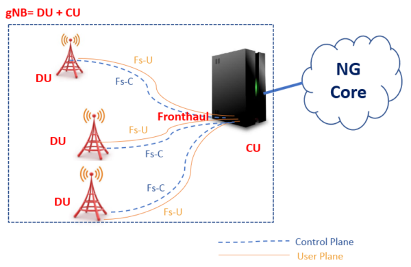
1 CU/DU Split Architecture
The gNB is split into a CU and DU for the scalability and DU offloading
In order to overcome an explosion in traffic usage, 5G largely makes use of higher frequency bands than LTE. Doing so introduces challenges in coverage due to the inverse relationship between frequency and cell coverage. Typically, small coverage cells result
in more frequent handovers for mobile users and this risks impacting quality of experience if not appropriately managed. If we can increase the number of cells being managed by each individual base station (gNB), then a greater number of handovers can be handled
through intra-gNB mobility which has a significantly smaller impact than inter-gNB mobility since the device’s anchor point remains the same. By separating this functionality from the Digital Unit (DU) and centralizing it towards the Central Unit (CU), we can increase the
number of cells being managed by each CU, and thus maximize the ratio of intra- vs inter-gNB handovers. At the same time, higher frequency bands also allow the use of wider bandwidth carriers and thus gNBs need considerably more traffic processing capacity
compared to LTE eNBs. Compounding on this, when Dual Connectivity is widely used in 5G networks, devices may connect to two different gNBs, but only one of these (the anchor DU) is responsible for processing the split data streams (via Packet Data Convergence
Protocol, or PDCP). Thus the PDCP load is concentrated on the PDCP anchor DU, which creates a load imbalance and inefficient resource usage between the PDCP anchor DU (over-utilised) and the non-anchor DU (under-utilised). To mitigate this load imbalance, PDCP aggregation needs to be off-loaded to the CU in a more central site where pooling /resource sharing can efficiently handle the task. For these reasons, 5G deployments are best served by a separated CU that is more centrally located from the DU.

vRAN CU (Central Unit)
● Non-Real time processing such as RRC, PDCP is off-loaded to the central site and the RRC, PDCP resource pool is shared between multiple DUs.
● CU can accommodate multiple DUs to build a large scale gNB.
● CU is typically virtualised on a COTS server for the scalability and flexibility.
vRAN DU (Distributed Unit)
● Real time processing such as RLC, MAC, PHY, RF need to remain close to the local site.
● DU is also virtualised on a COTS server for business agility.
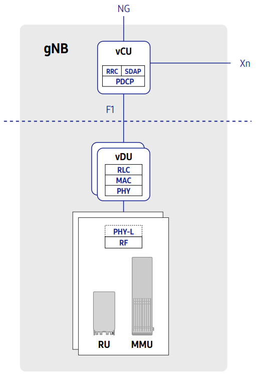
2 CU-CP/CU-UP Split Architecture
The gNB-CU is split into CP and UP for flexible dimensioning and topology
The new 5G services based around massive Machine Type Communications (mMTC), Ultra Reliable and Low Latency Communications (URLLC), Fixed Wireless Access (FWA), and new industry verticals will generate unique traffic patterns compared to typical mobile data service.
The Conventional DUs with fixed Control and User Plane (CU/UP) resources, which are typically designed to accommodate such ‘typical mobile data services’, are not well-suited to support the newer traffic patterns. Instead, a more flexible capability to dimension and scale directly in-line the traffic requirements of new types of services is needed. In particular, as Network Slicing and MEC are introduced, the UP should be divisible into multiple entities and allocated wherever needed for optimization of each specific services.

3 CU/DU Virtualisation
The CU and DU are virtualised for the enhanced scalability, flexibility and resource efficiency
Along withthe CU/DU split and CU-CP/CU-UP split, container technology can further enhance scalability, flexibility and resource efficiency.
3-1 CU Virtualisation
Each component in the vCU can have its own flavour (size) for flexible
dimensioning. Traffic loads for control and user planes are balanced
between each plane’s components separately to maximize resource
usage efficiency. Each component can be scaled on-demand or
automatically based on current load status.
3-2 DU Virtualisation
Each component in the vDU can have its own flavour (size) for flexible
dimensioning. DU components can be scaled out if additional cells
are deployed.


Benefits of Virtualised and Disaggregated RAN Architecture
Network evolution through Software upgrade
In traditional, hardware-oriented network solutions, the deployment of new standards, features and services often requires replacement of hardware, particularly when there are changes to lower layer protocols or when there is a need for increased processing capacity.
With Virtualisation of the RAN, in which L1/L2 functions are implemented purely through software, the expensive and time- consuming process of hardware replacement can be avoided. Furthermore, as capacity requirements grow due to increased traffic demand, generic off-the-shelf compute hardware can be added to the resource pool – a much more cost-effective proposition than swapping older proprietary hardware for newer proprietary hardware. The end result is that operators are better able to manage and maximize the
lifecycle of their hardware, match forecasted growth to CAPEX and reduce overall costs of ownership.
Adoption of well-developed IT technologies
By implementation of Network Function Virtualisation, operators can deploy and manage their network utilizing well -developed IT principles such as Software-Defined Networking, life-cycle management and CI/CD to minimize CAPEX and OPEX.
Scalable gNB beyond DU boundary
With a CU/DU split, the gNB can be scaled flexibly from small (single DU size) to large (accommodating multiple DUs, up to 2048 cells), agnostic of DU hardware types for various deployment environment (e.g. rural, dense urban, D-RAN, C-RAN, Small Cell, mmWave). This is in contrast to the conventional DU architecture, which presents limitations on gNB scale based on the capacity of individual DU hardware.
Mobility optimised vRAN architecture
In a conventional aggregated RAN, as users move around the boundary of different cells being served by different gNBs, service quality can often be degraded due to frequent inter-gNB handovers and packet forwarding between DUs. On the other hand, each CU in a disaggregated RAN can accommodate a much larger number of cells for each gNB, and itself becomes the mobility anchor point, greatly reducing the number of anchor point handovers that occur as users move between cells. For users, the key benefit is a noticeably improved quality of experience and more reliable mobility as inter-gNB
handovers and packet forwarding is reduced within the broader CU coverage footprint. When UE moves to neighbor cell, intra-gNB HO of CU/DU split architecture has no RRC/PDCP anchor change, no traffic forwarding during HO procedure and no HO signaling toward the Core Networks compared to inter-gNB HO of conventional DU architecture.

Flexibility in CU-UP deployment
The user plane of CU can be sliced into multiple CU-UPs to support network slicing and multiple CU-UPs can be deployed in independent locations while single CU-CP is deployed in the central site. For the network slicing and MEC scenarios such as low latency services or local-break out applications, CU-UP can be located close to DU while CU-UP for eMBB service remains in central site for the high capacity.

CP/UP independent dimensioning and scaling
With the CP/UP split along with CU virtualisation, CP/UP separated resource allocation and scaling enables to adapt to the traffic patterns which varies according to the services. (FWA, eMBB, mMTC etc.) For 5G network, traffic pattern will be complicated because new services with different usage will introduced. Conventional dimensioning typically designed for mobile service traffic pattern cannot adapt to these various traffic patterns of the new services. For example, mMTC services have high control traffic load and low user traffic load. FWA services have low control traffic load and high user traffic load. Flexible dimensioning and scaling of virtualised and disaggregated RAN well adapted to various traffic patterns can bring resource efficiency as well.

Resource efficiency via resource pooling
In some networks today, a centralised RAN (C-RAN) architecture has been implemented in order to provide benefits in terms of resource pooling, reduce hardware requirements and footprint at the edge and simplify network operations and management overall. However, conventional DUs create a type of hard-limit in the benefit that can be gained from a C-RAN deployment due to the fixed capacity of each DU and the static boundary between each piece of hardware. Through virtualisation of the DU functionality and separation of the network function from the hardware resources it requires, we gain the ability to flexibly allocate and scale resources independently and in a far more granular manner. For example, a conventional DU can experience severe load imbalance in some situations, such as separate DUs assigned between rural and urban areas, or in the case of anchor versus non-anchor DUs in a Dual Connectivity scenario. If we can instead pool the hardware resources independently of each DU function, we can flexibly assign resources to each DU only as needed, mitigating the potential for load imbalance to occur. Overall, this means that fewer resources are required due to gains in statistical multiplexing, i.e. there
is less need to provide emergency overload capacity individually for each DU. The flexible dimensioning and scale in/out features of vRAN which enable efficient resource pooling are described in the following section.

Flexible dimensioning with multiple flavours
The vCU (CU-CP, CU-UP) and vDU consist of several components. Specific components have a flavour set for flexible dimensioning. A flavour defines the amount of resources to support certain capacity or performance. vCU&vDU can be built with various combination of flavours considering required network performance and capacity. This flexible dimensioning based on network virtualisation enables optimization in constructing networks in terms of resources such as CPU core and memory.
Flavour Sets:

Automatic/on-demand scale in/out of vCU
According to the each control/user traffic decreases and increases, CP Component and UP Component can be scaled in/out automatically or on-demand manner. This scale in/out enables dynamic resource adaptation to control/user traffic change respectively. Furthermore, because each components share common resources for scaling, resources can be utilised efficiently.

On-demand scale in/out of vDU
As the vDU support on-demand scaling for the DU Component, it does not have to be allocated HW resource of maximum vDU capacity for further network growth at initial deployment stage. Instead, it can start with a number of DU Components only required for the initial deployment. When more cells are required, vDU can increase its cell capacity by scaling-out the DU Component.

L1/L2 acceleration on x86 server
The physical layer and MAC layer of a RAN consist of a set of functions with very high computational complexity: channel estimation and detection, Successive Interference Cancellation (SIC) for MIMO, Forward Error Correction (FEC), scheduling algorithms that handle resource allocation between users with different QoS requirements and channel conditions, and so on. Intel’s Advanced Vector Extension (AVX) instruction set can be applied to many of these functions – especially those related to signal processing that involve vector operations. To further increase the capacity of the vDU, some computation-intensive task with repetitive structures, such as FEC, may be off-loaded to an FPGA, which can be optionally installed into a COTS server via a PCIe interface.

Real time processing technique
User data received from the vCU (i.e. the downlink PDCP packets) passes through a chain of processes in the vDU to become physical layer packets. For successful transmission of these packets over the air, all processing must be completed before the designated time slot begins. Similarly in the uplink, the vDU recovers the information bit stream from the received uplink signals through channel estimation, demodulation and channel decoding, and sends a HARQ feedback to the corresponding user device within the given time budget. In order to meet this timing-stringent operation requirement, L1/L2 tasks in the vDU are carefully designed to be scheduled and completed. IT application software in general show unpredictable response times with a large deviation from the average. The figure below shows how such jittery processing times can affect vDU operation. In the case of conventional task scheduling, generated packets can frequently end up being discarded due to such unexpected delay, degrading link performance due to high packet loss rates.

Performance and capacity optimization
The efficient use of compute resources, as well as accelerated packet processing and networking, are crucial for a competitive vRAN design considering the large amount of data that vRAN must handle. One simple way to see this is to compare the fronthaul
bandwidth to the user traffic rate. For example, in 16-QAM, just four bits of user data turns into a pair of I/Q samples composed of about 20 bits to ensure reasonable performance in a noisy, fading channel. In essence, vRAN needs a much higher packet handling capability
for the radio-side interface than its backhaul interface. To get the best performance and capacity from x86-based COTS servers, our vRAN adopts various virtualisation techniques, including core pooling and pinning, DPDK and SR-IOV.
Telco grade reliability and availability
We note that in modern societies, it is easy to identify a growing reliance on communications across a variety of sectors, including business, finance and public safety. If a mobile communication service becomes unavailable for even a short period of time, serious collateral damage can result in terms of social disorder and monetary losses. To avoid such chaotic outcomes, each component of a network must maintain a high standard of telco-grade service availability and reliability – and the vRAN is no exception to this. Basic fault recovery and redundancy features commonly available in the IT domain are no sufficient. Our vRAN applies enhanced or newly designed health checks, fault recovery and geo-redundancy techniques to minimize service outages.
Introduction of Virtualised DU in 5G Networks
Virtualised DU for Network Slicing
Through network slicing, 5G networks can effectively and efficiently provide a wide variety of different service types (e.g., eMBB, URLLC, mMTC, etc.) in a given cell. Each network slice has its own service and performance requirement profile. For example, URLLC requires very low millisecond-scale latency and very high reliability in comparison to eMBB, where latency and reliability requirements or more relaxed but bandwidth is a key concern. In the case of mMTC on the other hand, individual traffic volumes are much lower, but
reliable device density is of prime importance. 5G networks must be capable of efficiently allocating hardware and radio resources for each of these separate services on a per-slice basis. While a traditional DU may be effective in the deployment of a large number
of high-bandwidth, wideband NR cells thanks to the high performance of dedicated hardware technologies such as application-specific integrated circuits (ASICs), as networks begin to target more diverse service types virtualised DUs capable of flexibly adapting to customised traffic profiles will prove to be a valuable and cost-efficient approach.

DU Separation for Secure Network Slice
Some network slice could need dedicated DUs separated from existing DUs to serve services like eMBB. For example, a security service could need extremely high security level to need separate DU not to eavesdrop traffic packets. In the following diagram, on top
of existing NR network, Virtualised DU is deployed for secure service slice. You can notice that RU is shared between two DUs through common layer.

Conclusions
The widely deployed distributed RAN was designed nearly 20 years ago in the pre-smartphone 3G era, when few would have foreseen the incredible volume and variety of traffic, devices, and applications that mobile networks carry today. While this outdated architecture has evolved to more centralised models, current solutions do not go far enough to address CSP challenges.
CSPs are under pressure to keep up with surging traffic demand and the influx of new devices and applications, while at the same time finding additional service revenue to stabilise ARPU and cut costs to protect profit margins.
By extending the benefits of NFV from the core network to the RAN, virtualised RAN is the optimal solution for cost-efficiently increasing capacity, reducing costs, and creating new services.
Various vendors have joined forces to create a pre-integrated solution that CSPs can deploy today to start reaping the benefits. The solution delivers carrier grade reliability and predictable performance, low-latency, unrivaled manageability and orchestration, massive scalability, optimised resource utilisation, and flexible deployment options as well as
the ability to quickly launch new services through network slicing and service chaining. The pre-integrated vRAN solution and comprehensive professional services mitigate deployment risk and accelerate time-to-market.
For Further Information
Please Contact Us