Do the new security and privacy features of 5G require a new SIM card? Simple answer is no. However, the complete answer is more complex.
SIM cards are Smart Cards with data
In this article, we refer to these newer smart cards as Rel 99+ USIM which are compatible with 3GPP Release 1999 (first 3G specifications) and afterwards. These Rel 99+ USIMs can be used to access every generation of mobile networks, including 5G. Such backward and forward compatibility is achieved by the carefully-designed offloading of some computations and storage to mobile phones.
5G Networks: Logo (C) 3GPP
While accessing the 5G system is one thing, the question we have is whether using the “new” security and privacy features of 5G requires a new kind of USIM other than Rel 99+ USIMs which could be used for 4G security. This is a valid question and something which we address below. For the sake of brevity, in this post, we do not touch upon other new features in 5G that do not concern USIM.
SIM Identity and access management (IdaM)
In 5G, subscription permanent identifier (SUPI) could be in two formats, one is the legacy format called international mobile subscriber identity (IMSI) and another is the format newly adopted in 5G called network access identifier (NAI). Furthermore, 5G provides at least two methods of authentication and key agreement (AKA) for accessing the network. One such method, 5G AKA, is an evolution of the authentication method in 4G. Another, called EAP-AKA’, is a method now widely adopted in 5G for broader use of the Extensible Authentication Protocol (EAP) framework.
In any case, from the IdaM viewpoint, the Rel 99+ USIMs that could be used in 4G are still compatible with 5G, in that they can be used to authenticate and gain access to the 5G system. The main reason for this forward compatibility is the fact that there is no need for a new permanent security key shared between USIMs and the network. Another reason is that newer storage and computations required for new security features can be offloaded to mobile phones, like the calculation of a new type of AKA response and new session keys.
The adoption of the EAP framework in 5G means that it is possible for other methods than EAP-AKA’, such as Extensible Authentication Protocol-Transport Layer Security (EAP-TLS), to be used for isolated deployments. In those cases, it could be such that the USIM’s role is skipped. It is also worth noting that, just as with 4G networks, any smart cards older than Rel 99+ USIM (which may be called Rel 98- SIM) cannot be used to access 5G.
5G SIM Privacy
5G has introduced significant privacy enhancements in terms of how permanent and temporary identifiers are used.
An important topic which is use of subscription concealed identifier (SUCI). The SUCI, which basically hides the SUPI over-the-air, can be calculated using standardized schemes like so-called Profile A and Profile B. It also requires some new parameters like public key of the home network, scheme identifier, and routing indicator. While SUCI calculations using Profile A/B can be offloaded to mobile phones, the standards only permit the storage of the new parameters in the USIM. For brevity, in this post we will not discuss the proprietary option where SUCI calculation can be done in USIMs using non-standardized schemes.
Therefore, Rel 99+ USIMs can be used to store the parameters required for SUCI calculation with Profile A/B given that they support creating the necessary files (DF5GS/EFSUCI_Calc_Info/EFRouting_Indicator). This is also true for Rel 99+ USIMs already in the field i.e. if they support some mechanisms like remote file management over-the-air (OTA), then they could be used for storing the parameters required for SUCI calculation with Profile A/B. Otherwise, SUCI will be calculated by mobile phones using the so-called “null-scheme” which is a dummy scheme and does not hide SUPI. In other words, Rel 99+ USIMs that cannot store new parameters required for SUCI calculation could still be used to get access to the 5G system but without the ability to hide the SUPI over-the-air.
Note that there are also other privacy enhancements in 5G like the strict refreshment of temporary identifiers, decoupling of permanent identifiers from paging procedures, and partial confidentiality protection of initial messages. For these features, the USIM’s role is not required in the standards.
Steering of roaming (SoR) and UE parameter update (UPU)
SoR and UPU are two new procedures in 5G between mobile phones and the home network. These new procedures enable the home network to update configuration parameters in mobile phones and/or USIM using control plane signaling. It means that, in 5G, the home network has an alternative to existing mechanisms like over-the-air (OTA) updates that use SMS as transport.
As well as handling of the so-called “secured packet” that mobile phones can basically relay to the USIM, the scope of SoR and UPU procedures include parameters like operator controlled PLMN selector with access technology, default configured network slice selection assistance information (NSSAI), and routing indicator.
Handling of new control plane signaling including security, like calculation and verification of new security tokens, are offloaded to mobile phones. Furthermore, in some cases, storage of parameters is also offloaded to mobile phones like default configured NSSAI and mobile phone’s copy of operator controlled PLMN selector with access technology. Therefore, in such cases, special support from the USIM is not required for SoR and UPU in 5G, which means that Rel 99+ USIMs can be used.
There are other cases when the storage of the new/updated parameters is still done in USIM, like routing indicator (EFRouting_Indicator), USIM’s copy of operator controlled PLMN selector with access technology (EFOPLMNwACT), and any file handling done by the “secured packet”. Even then, Rel 99+ USIMs are still compatible with SoR and UPU in 5G given that they support the necessary file management operations.
5G SIM card Summary
To summarize, impacts on USIMs by relevant security and privacy features that are new in 5G.
from IdaM viewpoint, Rel 99+ USIMs which could be used for 4G are still compatible to get access in 5G.
Regarding SUPI privacy, Rel 99+ USIMs can be used to enable SUCI calculation with Profile A/B as long as they support necessary file management operations. Regarding other privacy features, Rel 99+ USIMs are fully compatible in their current form.
From a perspective of SoR/UPU procedures, Rel 99+ USIMs are compatible in their current form only in some cases, while in other cases compatibility will depend on them supporting necessary file management operations.
Whether/how to use the above mentioned new security and privacy features is in the remit of the network operator and therefore, even in worst case, they will not prohibit access to the plethora of other basic 5G features.
Technical notes
IdaM part – The formats of SUPI (IMSI and NAI) are defined in 3GPP TS 23.003, see clauses 2.2A, 2.2, and 28.7.2. The new type of AKA response is called RES* and new session keys are called KAUSF and KSEAF. See clauses 6.1 in 3GPP TS 33.501 for details. In Annex B of that TS, you will also find details of using EAP-TLS
Privacy part – The formats of SUCI are defined in clauses 2.2B and 28.7.3 in 3GPP TS 23.003. Clause 6.12 and Annex C in 3GPP TS 33.501 contain main details of subscription identifier privacy. Clause 4.4.11 in 3GPP TS 31.102 specifies USIM files specific to 5G
SoR/UPU part – The new security tokens are called SoR-MAC-IAUSF, UPU-MAC-IAUSF, SoR-MAC-IUE, and UPU-MAC-IUE. See the main details of SoR and UPU can be found in clauses 6.14 and 6.15 in 3GPP TS 33.501, Annex C in TS 23.112, and Clause 4.20 in TS 23.502
Beamforming, Beam Steering & Beam Switching with Massive MIMO for 5G compared
Combining the high propagation loss of the millimeter wavelengths (mmWaves) employed in 5G new radio (5G NR) systems, plus the higher bandwidth demands of users, combinations of beamforming techniques and massive Multiple Input and Multiple Output (MIMO) are essential for increasing spectral efficiencies and providing cost-effective, reliable wireless network coverage.
Beamforming
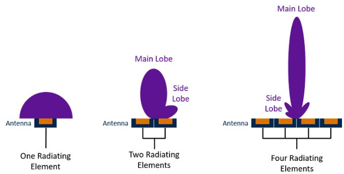
Beamforming is the application of multiple radiating elements transmitting the same signal at an identical wavelength and phase, which combine to create a single antenna with a longer, more targeted stream which is formed by reinforcing the waves in a specific direction. The general concept was first employed in 1906 for trans-oceanic radio communications.
With more radiating elements that make up the antenna, the narrower the beam. An artifact of beamforming is side lobes. These are essentially unwanted radiation of the signal that forms the main lobe in different directions. Poor engineering of antenna arrays would result in excessive interference by a beamformed signal’s side lobe. The more radiating elements that make up the antenna, the more focused the main beam is and the weaker the side lobes are.
Figure 1: Beamforming with two and four radiating elements
While digital beamforming at the baseband processor is most commonly used today, analog beamforming in the RF domain can provide antenna gains that mitigate the lossy nature of 5G millimeter waves.
Beam steering and beam switching
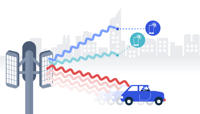
Beam steering is achieved by changing the phase of the input signal on all radiating elements. Phase shifting allows the signal to be targeted at a specific receiver. An antenna can employ radiating elements with a common frequency to steer a single beam in a specific direction. Different frequency beams can also be steered in different directions to serve different users. The direction a signal is sent in is calculated dynamically by the base station as the endpoint moves, effectively tracking the user. If a beam cannot track a user, the endpoint may switch to a different beam.
Figure 2: Beam steering and beam switching
This granular degree of tracking is made possible by the fact that 5G base stations must be significantly closer to users than previous generations of mobile infrastructures.
Massive MIMO
Multiple input and multiple output (MIMO) antennas have long been a feature of commercial public wireless and Wi-Fi systems, but 5G demands the application of massive MIMO. To increase the resiliency (signal-to-noise ratio / SNR) of a transmitted signal and the channel capacity, without increasing spectrum usage, a common frequency can be steered simultaneously in multiple directions.
The successful operation of MIMO systems requires the implementation of powerful digital signal processors and an environment with lots of signal interference, or “spatial diversity”; that is a rich diversity of signal paths between the transmitter and the receiver.
Figure 3: Multiple input and multiple output (MIMO)
Diversity of arrival times, as the signal is bounced from different obstacles, forms multiple time-division duplexing (TDD) channels that can deliver path redundancy for duplicate signals or increase the channel capacity by transmitting different parts of the modulated data. First conceived of in the 1980s, there are a few differences between classic multi-user MU-MIMO and Massive MIMO, but fundamentally it is still the large number of antennas employed and the large number of users supported. The degree of MIMO is indicated by the number of transmitters and the number of receivers, i.e. 4×4.
Conclusion
Beamforming, Beam Steering, Beam Switching and Massive MIMO are key ingredients for 5G base stations.
There’s currently huge controversy in the news today regarding safety of 5G: Is it safe, or not? 5G vendors & scientists say the technology is perfectly safe, and some members of the public allege that 5G isn’t safe. Here we examine the topics factually.
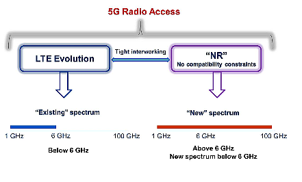
Frequencies used by 5G
There is nothing magic or new about the frequencies used or proposed for 5G. They have ALL been used already, actually for decades! 5G frequencies are split into two sections: FR1 (less than 6GHz) and FR2 (high frequency microwave, or “millimeter wave”).
Almost ALL of the FR1 frequencies have already been used for 4G, and some before that for 3G, and 2G, back to the 1990’s. A good example is 900MHz (the original GSM system) and 1800MHz (second round of GSM). 2100MHz was used extensively for 3G. A few of the FR1 frequencies haven’t been used for 4G before (e.g. 3800 up to 4200MHz) but they have been used for other purposes before.
FR2 frequencies (millimeter wave, or mmWave) have already been used – very widely – for Point-to-Point microwave links. All of the FR2 bands (24Ghz, 26GHz, 28GHz, 38-40GHz, and even the proposed 60GHz) have been used for point-to-point terrestrial microwave links. Those are the parabolic dishes you see everywhere on rooftops or towers. These signals are highly directional “pencil beams” with typically 1 degree or less beam width. The number of these links globally is in the 100,000+ range: they are beaming signals around cities all over the world, usually connecting internet services, beaming signals up to 3G/4G towers or for links between corporate office networks. As a result of the creation of 5G technology, these frequencies are now being re-used (“re-farmed”) for use by 5G base stations to connect end users to the internet, using Point-to-multipoint beamforming technologies. Important note: the use of 5G is no more or less “scary” than the previous use for point to point links. Note that point-to-point microwave has existed since 1930: 90 years ago, and health risks (and lack of risk to public) are very well understood.
Operating Distances
5G in lower frequencies travels longer distances than higher frequencies, due to laws of physics. This is why the lower frequencies are used for Rural locations for wide area coverage, whereas the higher frequencies are reserved for use in cities, where distances are shorter, and user densities higher.
Also, the lower frequencies (lower end of FR1) can be transmitted at higher power levels than the higher frequencies. Conversely, high frequencies (mmWave, FR2) are limited to lower power due to limitation of today’s commercial technology.
5G in the 24GHz, 26GHz, 28GHz range and above (also called millimeter wave, or mmWave bands) uses higher frequencies than 4G. As a result, these high frequency 5G signals are not capable of traveling large distances (over a few hundred meters), unlike 4G or lower frequency 5G signals (sub 6 GHz) so penetration and hence coverage are lower. This higher frequency therefore requires placing 5G base stations every few hundred meters in order to use higher frequency bands.
5G and RF power levels
Some of the “5G Conspiracists” allege that 5G will cause damage/health risk to humans. There is simply no measured case or evidence of this happening. If there were, there would be scientists & health advisors demanding change. Let’s examine in more detail:
5G sites using FR1 transmit at exactly the SAME power levels as 4G sites. So you’re not irradiated any more than a 4G site was. 40W a typical figure for a macro (big) site, and 1W for a Small Cell (small site). Note carefully: 5G FR1 sites use EXACTLY the same power levels as 4G sites, which is similar to 3G sites, and before that, 2G sites … 5G uses “sector antennas” (typically 3 on a macro site) just like 4G does. Therefore any related health risk is therefore the same for 5G as it’s predecessors.
5G sites using FR2 transmit at MUCH lower power levels: less than 1 Watt typically. These high frequency signals have poor penetration of buildings and obstacles, so are generally “line of sight” only. As noted above, ALL of the FR2 frequencies have been used before, for terrestrial microwave links, and at similar power levels (less than 1 Watt). The use of beamforming steers the signal to the required locations; this reduces the overall amount of transmitted power emitted into the air, and hence total radiation. Put simply, if you aren’t using your device, the base station doesn’t point power at you.
How to 5G power levels compare to other Radio/RF transmitters?
The VERY good question conspiracists & “truthers” never discuss. Let’s go straight there.
A TV transmitter such as Crystal Palace in London, UK currently transmits digital terrestrial Television at over 1200kW (1.2 MEGAWATT, or 1,200,000 watts), and has been transmitting TV since 1956. That is 120 MILLION TIMES more power than a V-band 60GHz radio, and transmitting for over 60 years. Did you hear “5G protesters” complaining about TV transmitters? No, because there’s no widespread history of health effects over 60 years .
Airport Radars: To keep planes flying safely, airport radars transmit pulses up to 25kW (25 kilowatts, or 25,000 Watts) into the air, with average power 2.1kW (2100 Watts). Interestingly, these signals are at similar frequencies to 3G, 4G and 5G. In the USA, 2.7 – 2.9 GHz is used. Yet nobody complains about these high power levels of radar, which has been in constant use since the 1930s: 90 years.
Digital Radio (DAB): Crystal Palace transmits digital radio with 18kW (18,000 Watts) of radio power. Compare that with 40W of a large (macro) 5G base station.
Emergency Service (TETRA) Radios : used by police, fire & ambulances: transmit at up to 45 Watts. Very similar to the 40W of a large (macro) 5G base station.
You will notice that the HIGHEST powered transmitters are Television transmitters (Megawatt), Radars & Radio stations (10’s of Kilowatts). A macro 5G base station at 40W comes nowhere close. Note that these various transmitters are used on different frequencies, there’s no “one” frequency that is safer (or less safe) than another. It’s only the RF exposure (power) level that matters – specifically, the power incident on your own human body.
Why is there no mass hysteria from “Truthers” about TV, Radar and Radio transmitters? Because if they were THAT bad for our health, they would have been banned and switched off decades ago. Evern the largest (macro) 5G transmit powers are tiny by comparison.
Key “Truther” points examined:
60GHz is absorbed by Oxygenin the bloodstream (Untrue) Out in the open airthis absorption is true : but not in the body! 60GHz signals are 40% reflected by skin surface, absorbed by water (body is 60% water), and does NOT enter the bloodstream. The “Truthers” invent Pseudo-science , claiming: “This causes Oxygen to not bind well to blood hemoglobin causing the body to become Oxygen starved (hypoxia)” This statement is hopelessly unscientific. The ultra low power 60GHz signals do not even penetrate human skin. The signals are partly reflected and partly absorbed by the skin, preventing them entering the body and cannot cause the claimed effect. There is NO scientific study which will back up this claimed hypoxia effect on the human body. The “5G protesters” NEVER provide any, because there is no publication or science that would agree with their unscientific claims – it’s simply not impossible. They make stuff up to make you afraid, and sharing their website gives them more “hits”: Some have adverts on their sites. More clicks means more money for them! (Fear=money for some)
5G is a state-sponsored weapon: Untrue. 5G is simply a marketing term applied to the work of the 3GPP, a standards body which includes equipment vendors & operators, as a linear development of from work that was labelled 4G and 3G before it. Governments are not included in developing 2G, 3G, 4G, 5G… and future 6G technology – corporations are.
Governments want to use 5G to control the population: Untrue, in that 5G gives Government agencies no more data than 4G does. Your location, digital activities, content & data usage habits are already well known to Google, Facebook and – on warrant – Law Enforcement Agencies. 5G does not change this at all. You already gave all that data to companies 10 years ago when you bought a 3G smartphone, or signed up with Social Media sites, apps, Apple or Google services. Law enforcement agencies can demand access to that data with a warrant.
IoT is scary: Untrue, in any way that relates to 5G. “Internet of Things” is a marketing label applied to home gadgets – and industrial devices – that are connected via the Internet by either WiFi or cellular (4G, 5G) networks. The same IoT label applies to a WiFi doorbell. Main concern with IoT is DATA security, particularly physical security (locks, cars) and CCTV camera feeds. That has nothing to do with 5G, because the concern is the data security of the devices & security attitudes of companies that sell them. Note that the WiFi-connected IoT devices are a much greater security risk than 4G, 5G because WiFi is much easier for criminals to hack/spoof.
5G causes cancer: Untrue. 5G uses the same signals as 4G (FR1), plus some millimeter wave frequencies (FR2) which were previously used by microwave links for decades. There is no link to cancer in 30+ years of medical research and continued exposure to these signals. Microwave & radio signals used by 4G & 5G are NON-ionising radiation which is not hazardous except in massively high power levels (far more than 4G, 5G etc). The “dangerous” radiation type is IONISING radiation, including X-rays and similar. Those are not used for communication for this exact reason: they are dangerous. (Side-note: X-Rays used in medicine are VERY carefully controlled. Had an X-Ray? note the operators have shielding everywhere, because they use it every day & could get higher does than patients. They regulate the dose to you carefully for your safety)
5G is linked to Coronavirus: Untrue. There’s no link at all. Many of the countries with terrible cases of Coronavirus have no 5G. And vice versa. All the theories connecting the two have been soundly debunked by reputable & international scientists. (Side note: there IS a link between Coronavirus deaths and air pollution: because the Coronavirus effect on the body attacks the lungs, putting patients with poor respiration are at great risk. Cleaning up diesel emissions, industrial cities & banning smoking would have saved 1000’s of lives from Coronavirus.)
Power levels and Distance (very important topic)
The RF power emitted from the transmitter antenna spreads with distance. This means that a person some distance away from the tower only receives a weak signal. As you DOUBLE the distance, you receive one QUARTER the power level. This is called the “inverse square law”. What it means in practice is that a person 100’s of metres away from a base station is radiated with only microwatts of power, which is insignificant, especially compared to this next point:
The highest radiation of Radio signals you will get is from …. wait for it … Your cellphone is on your person – and when used in the worst case, held directly against your head. The cellphone transmits at up to 1 Watt power – in all directions – which means the signals go into your head as well as the air around you. This topic remains the same since the first cordless phones in the 1980’s, analogue cellphones and GSM phones in the 1990’s. Using the phone means the signal is close to your head – and the most sensitive item, your brain. The HIGHEST amount of radiation you will receive from any wireless system is from your OWN HANDSET when you hold it to your head to make a voice call. Therefore, if you are really worried about cellphone safety – STOP using your OWN phone. The radiation your body receives from it is 1000’s of times stronger than that you receive from the mast.
If you’re worried about 2G, 3G, 4G, 5G masts: stop now. The FIRST thing you must do is switch off your OWN phone, and never hold it against your head to talk. And if it’s in your pocket/jacket/handbag do remember, it’s still transmitting to the mast, updating it’s location to the network, and often up/downloading data to your apps continually. It’s still transmitting, even in “standby”. If you’re not prepared to turn off your OWN PHONE, then stop worrying about masts at all. The signal from masts signal is over 1000 times weaker than your OWN PHONE when it reaches your body.
Diagram courtesy Qualcomm
5G FR2 mmWave Penetration
Also, these higher frequency 5G signals cannot penetrate solid objects easily, such as cars, trees, and walls, because of the nature of these higher frequency electromagnetic waves. 5G cells can be deliberately designed to be as inconspicuous as possible, which finds applications in places like restaurants and shopping malls.
It is the responsibility of the 4G/5G cellular industry, national regulators, safety agencies and all academics to be truthful about the safety of all radio transmitters. There must be no cover-ups, lying, or partial truths. Medical research into possible risks of RF exposure must continue and be well funded. The industry needs to deliver reliable cellullar service without putting populations at risk. “Profit” cannot come at cost of public safety.
Conversely – “truthers” making up pseudo-science & invented “facts”, with blogs written by uneducated persons have so far resulted in:
Violence and threats against telecom employees doing their jobs on sites
4G/5G sites being burned down (resulting in loss of service to Hospitals, including those treating Coronavirus and critical health conditions)
Death threats and threats of violence against business owners.
Now think clearly and rationally: EVERYONE has a legal & moral responsibility to behave within the law and not to threaten the health of others. Clearly those posting non-factual “truther” content on Internet websites & social medahave a responsibility to bear. If you are one of those authors, think carefully. Your action could well cause harm or death of others.
I simply don’t believe you!
That’s the frequent response of someone when confronted with information that conflicts with their previously held opinion or prejudices. In the case of 5G, we have we have plenty of information sources. On the “5G is safe” side we have:
All reputable Scientists Worldwide
All national Governments
Biologists Worldwide
All safety Agencies Worldwide
The Cellphone industry
30+ years of no measurable health effects of cellphones on worldwidepopulation
And on the “5G is unsafe” side we have:
Conspiracists without facts
Non-scientific blog writers, some whom earn $ from adverts on their blogs (!)
Narcissists who want “likes” on posts, or TV appearances
Easily-swayed but highly opinionated people
NO evidence of health effects over 30+ years
NO reputable scientists !
Have a careful think about what sources of information you take in forming your world view. Just two hundred years ago, our ancestors burned and drowned innocent people for “witchcraft”. Why are we any better informed than our ancestors? Answer: SCIENCE and EDUCATION. We use logic, rather than irrational and uninformed fear.
Conclusion for 5G & Safety
There is a huge media frenzy and “truther sites” full of pseudo-science about 5G & safety. We suggest we make our decisions based on science and facts. Here’s our summary:
5G is no less safe than 4G. If you didn’t protest 4G, stop protesting 5G.
(If you DID protest 4G, then carry on protesting, but remember, 5G is no less safe!)
“Millimeter wave” frequencies have already been used for 3 decades or more for terrestrial microwave links. We’ve already been irradiated by them for 30+ years, with no harm to us. 5G just re-uses these same frequencies.
There is no measured health risk from “Millimeter Wave” signals in any credible study or publication. 60GHz doesn’t stop O2 in the blood, that’s a non-scientific myth invented by “truther” blogs. No medical reports or science to back up claims.
“Millimeter wave” (FR2) transmitters are on average 50x less powerful than the lower frequency FR1 macro (main site) transmitters.
The HIGHEST radiation you will get is from your OWN cellphone: it’s right next to your body, and transmits even in your pocket/jacket/handbag. If you’re worried, turn it off.
Turning off 5G transmitters on masts makes AlMOST NO DIFFERENCE because the 2G, 3G, 4G transmitters on the mast are still transmitting, all at very similar power levels and frequencies, and distance to you is the same. Power levels radiated to your body remains almost unchanged whether you turn 5G on or off.
Turning OFF all the cellphone masts will cause deaths. A LOT of them, as your loved ones can’t dial an ambulance, lost persons, persons caught in fires & crash victims can’t call help. Emergency responders also rely on the masts. Conversely, there’s no measured death rate from cellphone masts, in over 40 years of widespread use.
LOGIC as well as ETHICS says leave the masts turned on.
For Further Information
If you are interested in 5G Health & Safety: Please Contact Us
5G in the 24GHz, 26GHz, 28GHz range and above (also called millimeter wave, or mmWave bands) uses higher frequencies than 4G. As a result, these high frequency 5G signals are not capable of traveling large distances (over a few hundred meters), unlike 4G or lower frequency 5G signals (sub 6 GHz) so penetration and hence coverage are lower. This higher frequency therefore requires placing 5G base stations every few hundred meters in order to use higher frequency bands.
5G FR2 mmWave Penetration
Also, these higher frequency 5G signals cannot penetrate solid objects easily, such as cars, trees, and walls, because of the nature of these higher frequency electromagnetic waves. 5G cells can be deliberately designed to be as inconspicuous as possible, which finds applications in places like restaurants and shopping malls.
Transmissions in mmWave bands suffer from significantly higher path loss and susceptibility to blockage. In addition, mmWave RF complexity makes meeting the cost and power constraints of mobile devices extremely challenging, which is why mmWave for mobile communications has historically been not feasible—until now. 5G NR mmWave is changing this.
Uses for 5G mmWave
While the initial focus for mobile operators is to quickly expand network capacities by starting deployments of 5G NR mmWave in existing dense urban markets, there are even more opportunities for mmWave beyond traditional macro networks. One area of interest is to bring mmWave indoors to address the exploding demand of fiber-like wireless broadband access in crowded venues, such as convention centers, concert halls, and stadiums. These venues have traditionally been challenged with limited network capacity, thereby constrained with the quality of service (e.g., slow speeds and unreliable connectivity) they can deliver. With mmWave’s significantly wider bandwidth and high spatial multiplexing gains, mobile operators and service providers could rapidly make multi-Gigabit, low-latency connectivity available to a large number of users.
Another exciting opportunity for mmWave is for private indoor enterprises, including offices, shop floors, meeting rooms and more. Imagine having virtually unlimited capacity and fiber-like wireless connectivity for your devices at work, no matter if it’s a smartphone, tablet, laptop, or mobile extended reality (XR). For these indoor deployment scenarios, we have also performed extensive study to show that significant coverage (i.e., >90%) and multi-Gbps median speeds can be achieved simply by co-siting mmWave small cells with existing LTE or Wi-Fi access points.
For Further Information
If you are interested in 5G Deployment Solutions: Please Contact Us
Massive MIMO (mMIMO) and beamforming are key acronyms widely used in the telecom industry when referring to 5G and latest advancements of 4G LTE. We note that MIMO comes in many different variants, some of them having been in use already for years in today’s 4G LTE networks.
SU-MIMO vs. MU-MIMO
In 4G LTE, the term MIMO usually refers to Single User MIMO (SU-MIMO). In Single User MIMO, both the base station and UE have multiple antenna ports and antennas, and multiple data streams are transmitted simultaneously to the UE using same time/frequency resources, doubling (2×2 MIMO), or quadrupling (4×4 MIMO) the peak throughput of a single user.
In MU-MIMO, base station sends multiple data streams, one per UE, using the same time-frequency resources. Hence, MU-MIMO increases the total cell throughput, i.e. cell capacity. The base station has multiple antenna ports, as many as there are UEs receiving data simultaneously, and one antenna port is needed in each UE.
Beamforming: principles of operation
The terms beamforming and mMIMO are sometimes used interchangeably. One may consider that beamforming is used in mMIMO, or beamforming is a subset of mMIMO. In general, beamforming uses multiple antennas to control the direction of a wave-front by appropriately weighting the magnitude and phase of individual antenna signals in an array of multiple antennas. That is, the same signal is sent from multiple antennas that have sufficient space between them (at least ½ wavelength). In any given location, the receiver will thus receive multiple copies of the same signal. Depending on the location of the receiver, the signals may be in opposite phases, destructively averaging each other out, or constructively sum up if the different copies are in the same phase, or anything in between. Beamforming is further divided to subcategories as explained in the following chapters.
Diagram courtesy Qualcomm
Digital beamforming (Baseband beamforming, precoding)
In this scenario, the signal is pre-coded (amplitude and phase modifications) in baseband processing before RF transmission. Multiple beams (one per each user) can be formed simultaneously from the same set of antenna elements. In the context of LTE/5G, MU-MIMO equals to digital beamforming. Multiple TRX chains, one per each simultaneous MU-MIMO user, are needed in the base station. Digital beamforming (MU-MIMO) is used in LTE Advanced Pro (transmission modes 7,8, and 9) and in 5G NR. Digital beamforming improves the cell capacity as the same PRBs (frequency/time resources) can be used to transmit data simultaneously for multiple users.
Analog beamforming
Here, the signal phases of individual antenna signals are adjusted in RF domain. Analog beamforming impacts the radiation pattern and gain of the antenna array, thus improves coverage. Unlike in digital beamforming, only one beam per set of antenna elements can be formed. The antenna gain boost provided by the analog beamforming overcomes partly the impact of high pathloss in mmWave. Therefore analog beamforming is considered mandatory for the mmWave frequency range 5G NR.
Hybrid beamforming
Hybrid beamforming combines the analog beamforming and digital beamforming. It is expected that mm-wave gNB (5G base station) implementations will use some form of hybrid beamforming. One approach is to use analog beamforming for coarse beamforming, and inside the analog beam use a digital beamforming scheme as appropriate, either MU-MIMO or SU-MIMO.
Massive MIMO
Most common definitions are that mMIMO is a system where the number of antennas exceeds the number of users. In practice, massive means there are 32 or more logical antenna ports in the base station It is expected that NEMs will start with a maximum of 64 logical antenna ports in 5G.
This diagram illustrates how mMIMO works in practice. An antenna array of 50 omni elements, with ½ wavelength spacing in between the antenna elements is used. The 50 elements transmit 4 distinct streams of data via 4 logical antenna ports, one stream for each UE. All four streams are transmitted using the same physical resource blocks, i.e. the same time/frequency resources. The data streams do not interfere between each other because each of them has a distinct radiation pattern, where the signal strength in the direction of the target UE is optimized, and in the directions of the other UEs (victim UEs) the signal strength is minimized.
In MU-MIMO/mMIMO, the base station applies distinct precoding for the data stream of each UE where the location of the UE, as well as the location of all the other UEs, are taken into account to optimize the signal for target UE and at the same time minimize interference to the other UEs. To do this, the base station needs to know how the downlink radio channel looks like for each of the UEs.
Common Public Radio Interface (CPRI) has been around for quite some time. But now, enhanced CPRI (eCPRI) is becoming an important technology to understand for 5G.
Before looking in detail at eCPRI, it’s helpful to understand some of the basic topology of the cellular network, which currently uses CPRI.
CPRI, Remote Radio Heads (RRH) in 4G and 5G
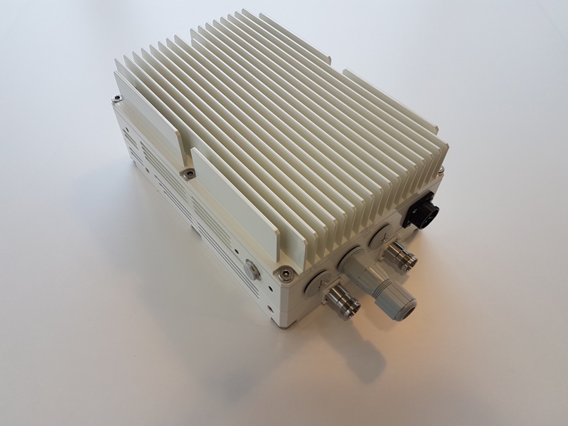
5G Remote Radio Head (RRH) with CPRI or eCPRI fibre optic interface
At the outer circle of a cellular network topology, remote radio units (RRUs) are distributed every few miles in cities and suburban areas. These RRUs comprise antennas and also some compute functionality.
Fiber runs from a cluster of these RRUs to connect to a more centralized baseband unit. The baseband unit is also sometimes called the “central processing unit.” Baseband units are typically distributed within approximately 10-mile circles for good coverage in populated areas. The connection between the RRUs and the base station is often referred to as “fronthaul.”
eCPRI
CPRI is an interface that sends data from the RRUs to the baseband unit: CPRI is a serial interface, which is a very high-speed connection, a way to translate all those radio signals back to the computing function.
As we go to 5G, the fiber between the RRUs and the baseband unit is going to carry much more traffic, and that makes it more difficult to do a serial interface. Extreme 5G requirements are stretching the limits of fiber bandwidth.
Enter eCPRI, which is a way of splitting up the baseband functions and putting some of that functionality in the RRU to reduce the burden on the fiber.
AT&T is among many carriers that are working on eCPRI. AT&T has made “the world’s first” eCPRI connection for mmWave at its 5G Labs in Redmond, Washington. AT&T made calls testing eCPRI, using systems from both Nokia and Samsung Electronics America.
This opens the door for higher network throughput with less fiber, which will create more efficient mmWave deployments, among other benefits, This is also a significant step in creating an open architecture within the radio access network (RAN).
Vendor lock-in
Another problem with the CPRI interface today is that it has become a proprietary technology.
In addition to supporting more bandwidth across fewer fibers, the enhanced CPRI also addresses the proprietary concerns. eCPRI will be an open interface, making it easier for carriers to mix and match vendor equipment for their RRUs and their baseband units.
Historically, because each vendor would have its own implementation of CPRI, it became proprietary. This forces carriers to buy both their RRUs and their baseband unit from the same vendor in order for the interface to work. With O-RAN this interface will be open. Carriers such as AT&T who implement eCPRI will be able to run equipment from different vendors, or even generic off-the-shelf equipment.
However, existing networks with CPRI installed will most likely remain in place for years to come.
For Further Information
To find out more about CPRI and eCPRI, please Contact Us
This article explains details of the 5G gNodeB (gNB) architecture and choices for Central Unit (CU) and Distributed Unit (DU) Split (CU DU Split)
How is the gNodeB Comprised?
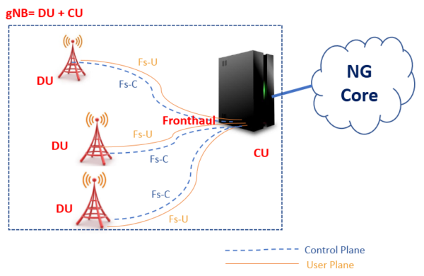
The logical architecture of gNB is shown in figure below with Central Unit (CU) and Distributed Unit (DU). Fs-C and Fs-U provide control plane and user plane connectivity over Fs interface.
In this architecture, Central Unit (CU) and Distribution Unit (DU) can be defined as follows:
Central Unit (CU): It is a logical node that includes the gNB functions like Transfer of user data, Mobility control, Radio access network sharing, Positioning, Session Management etc., except those functions allocated exclusively to the DU. CU controls the operation of DUs over front-haul (Fs) interface. A central unit (CU) may also be known as BBU/REC/RCC/C-RAN/V-RAN
Distributed Unit (DU): This logical node includes a subset of the gNB functions, depending on the functional split option. Its operation is controlled by the CU. Distributed Unit (DU) also known with other names like RRH/RRU/RE/RU.
The CU DU Split options:
Central Unit (CU) and Distributed Unit (DU) Functional Split Options
As a part of study item for New Radio (NR), 3GPP started studying different functional splits between central and distributed units. For the initial phase, 3GPP has taken LTE protocol stack as a basis for the discussion, until RAN2 defines and freezes the protocol stack for New Radio (NR). They have proposed about 8 possible options shown in below figure.
Option 1 (RRC/PCDP 1A-like split)
Option 2 (PDCP/RLC Split 3C-like split)
Option 3 (High RLC/Low RLC split, Intra RLC split)
Option 4 (RLC-MAC split)
Option 5 (Intra MAC split)
Option 6 (MAC-PHY split)
Option 7 (Intra PHY split)
Option 8 (PHY-RF split)
Option 1 (RRC/PDCP, 1A-like split): In this split option, RRC is in the central unit while PDCP, RLC, MAC, physical layer and RF are kept in the distributed unit. Thus the entire user plane is in the distributed unit.
Option 2 (PDCP/RLC split): Option 2 may be a base for an X2-like design due to similarity on U-plane but some functionality may be different e.g. C-plane since some new procedures may be needed. There are two possible variants available in this option.
Option 2-1 Split U-plane only (3C like split): In this split option, RRC, PDCP are in the central unit. RLC, MAC, physical layer and RF are in the distributed unit.
Option 2-2: In this split option, RRC, PDCP are in the central unit. RLC, MAC, physical layer and RF are in the distributed unit. In addition, this option can be achieved by separating the RRC and PDCP for the CP stack and the PDCP for the UP stack into different central entities.
Option 3 (High RLC/Low RLC Split): In this option, two approaches are taken based on Real time/Non-Real time functions split which are as follows:
Option 3-1 Split based on ARQ
Option 3-2 Split based on TX RLC and RX RLC
Option 3-1 Split based on ARQ
Low RLC may be composed of segmentation functions;
High RLC may be composed of ARQ and other RLC functions;
This option splits the RLC sublayer into High RLC and Low RLC sublayers such that for RLC Acknowledge Mode operation, all RLC functions may be performed at the High RLC sublayer residing in the central unit, while the segmentation may be performed at the Low RLC sublayer residing in the distributed unit. Here, High RLC segments RLC PDU based on the status reports while Low RLC segments RLC PDU into the available MAC PDU resources.
Option 3-2 Split based on TX RLC and RX RLC
Low RLC may be composed of transmitting TM RLC entity, transmitting UM RLC entity, a transmitting side of AM and the routing function of a receiving side of AM, which are related to downlink transmission.
High RLC may be composed of receiving TM RLC entity, receiving UM RLC entity and a receiving side of AM except for the routing function and reception of RLC status reports, which are related to uplink transmission.
Option 4 (RLC-MAC split): In this split option, RRC, PDCP, and RLC are in the central unit. MAC, physical layer, and RF are in the distributed unit.
Option 5 (Intra MAC split)
Option 5 assumes the following distribution:
RF, physical layer and lower part of the MAC layer (Low-MAC) are in the Distributed Unit
Higher part of the MAC layer (High-MAC), RLC and PDCP are in the Central Unit
Therefore, by splitting the MAC layer into 2 entities (e.g. High-MAC and Low-MAC), the services and functions provided by the MAC layer will be located in the Central Unit (CU), in the Distributed Unit (DU), or in both. An example of this kind distribution given below.
In High-MAC sublayer the centralized scheduling in the High-MAC sublayer will be in charge of the control of multiple Low-MAC sublayers. It takes high-level centralized scheduling decision. The inter-cell interference coordination in the High-MAC sublayer will be in charge of interference coordination methods such as JP/CS CoMP.
In Low-MAC sublayer the time-critical functions in the Low-MAC sublayer include the functions with stringent delay requirements (e.g. HARQ) or the functions where performance is proportional to latency (e.g. radio channel and signal measurements from PHY, random access control). It reduces the delay requirements on the fronthaul interface. Radio specific functions in the Low-MAC sublayer can for perform scheduling-related information processing and be reporting. It can also measure/estimate the activities on the configured operations or the served UE’s statistics and report periodically or as requested to the High-MAC sublayer.
Option 6 (MAC-PHY split): The MAC and upper layers are in the central unit (CU). PHY layer and RF are in the DU. The interface between the CU and DUs carries data, configuration, and scheduling-related information (e.g. MCS, Layer Mapping, Beamforming, Antenna Configuration, resource block allocation, etc.) and measurements.
Option 7 (Intra PHY split): Multiple realizations of this option are possible, including asymmetrical options which allow obtaining benefits of different sub-options for UL and DL independently.
This option requires some kind of compression technique to reduce transport bandwidth requirements between the DU and CU.
In the UL, FFT, and CP removal reside in the DU and for the two sub-variants, 7-1 and 7-2 are described below. Remaining functions reside in the CU.
In the downlink, iFFT and CP addition reside in the DU and the rest of the PHY resides in the CU.
Considering above there are three sub-variant available for this option described as below
Option 7-1 In this option the UL, FFT, CP removal and possibly PRACH filtering functions reside in the DU, the rest of PHY functions reside in the CU. In the DL, iFFT and CP addition functions reside in the DU, the rest of PHY functions reside in the CU.
Option 7-2 In this option the UL, FFT, CP removal, resource de-mapping and possibly pre-filtering functions reside in the DU, the rest of PHY functions reside in the CU. In the DL, iFFT, CP addition, resource mapping and precoding functions reside in the DU, the rest of PHY functions reside in the CU.
Option 7-3 (Only for DL): Only the encoder resides in the CU, and the rest of PHY functions reside in the DU.
Option 8 (PHY-RF split): This option allows to separate the RF and the PHY layer. This split permit centralization of processes at all protocol layer levels, resulting in very tight coordination of the RAN. This allows efficient support of functions such as CoMP, MIMO, load balancing, mobility.
Benefits of RAN Spilt Architecture
Some of the benefits of an architecture with the deployment flexibility to split and move New Radio (NR) functions between central and distributed units are below:
A split architecture (between central and distributed units) allows for coordination for performance features, load management, real-time performance optimization, and enables NFV/SDN
Configurable functional splits enables adaptation to various use cases, such as variable latency on transport
Which CU DU split function to use where?
The choice of how to split New Radio (NR) functions in the architecture depends on some factors related to radio network deployment scenarios, constraints and intended supported services. Some examples of such factors are:
Support of specific QoS per offered services (e.g. low latency, high throughput)
Support of specific user density and load demand per given geographical area (which may influence the level of RAN coordination)
Availability transport networks with different performance levels, from ideal to non-ideal
Application type e.g. Real-time or Non- Real Time
Features requirement at Radio Network level e.g. CA, eICIC, CoMP etc.
Reference: 3GPP TR 38.801 Radio Access Architecture and Interfaces Release 14
For Further Information
For more information on 5G Networks, gNodeB Architecture and CU DU Split, Please Contact Us
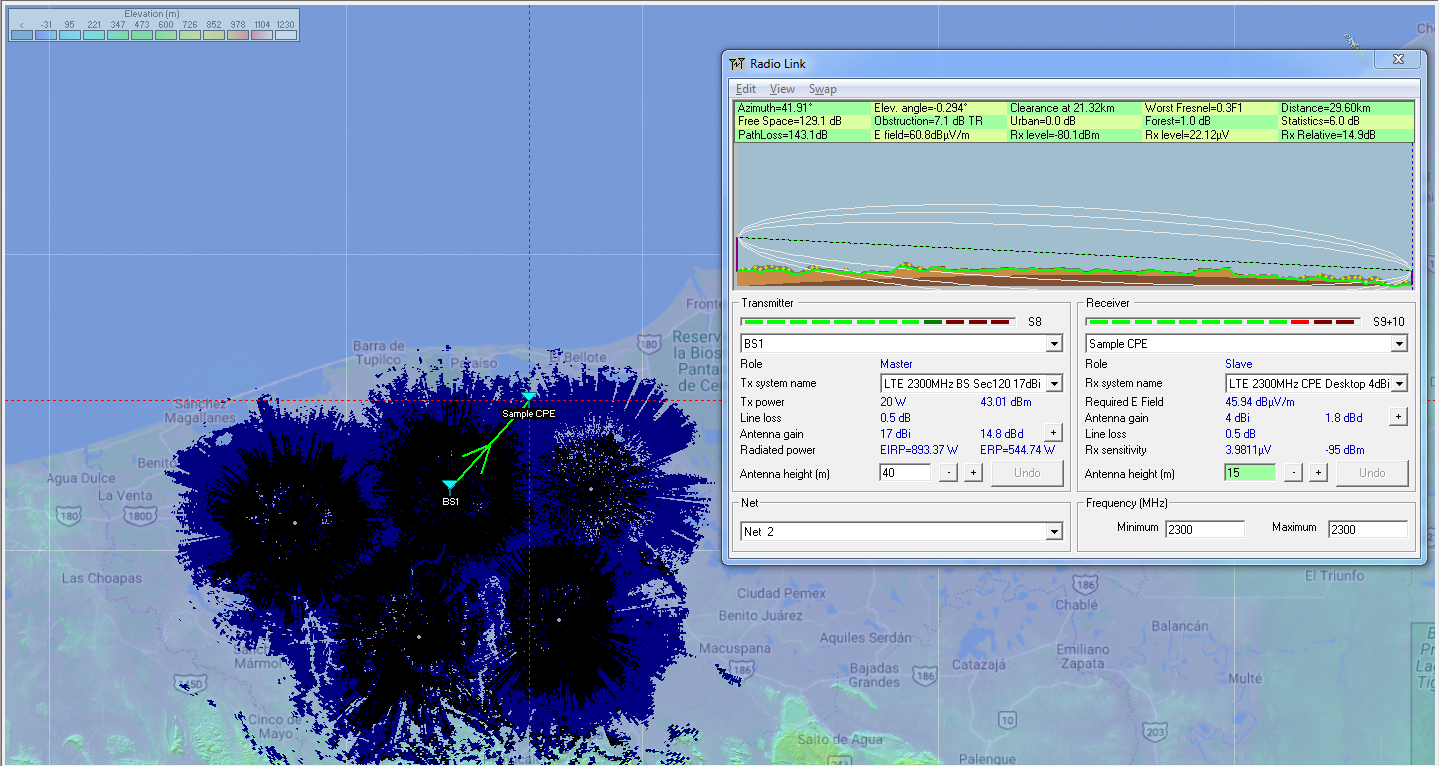
RadioMobile: Popular software for 5G Network Coverage planning
RadioMobile is a widely-available software package which can be used for 5G Network Coverage planning, including path profiling and clearance criteria, power budgets, choosing antenna sizes and tower heights.
For website for RadioMobile, please see this link here:
RadioMobile functions
For 5G Coverage Planning, the software package can be configured with the characteristics of your required radio network.
Transmit Power
Frequency Band
Antenna Gain
Receiver Sensitivity
Antenna heights
System losses
CPE types and locations
CableFree RadioMobile 5G LTE Coverage Planning example
Link Budget & Fade Margins
The software enables quick and rapid calculation of link budget and fade margins for any frequency band.
Terrain Database
The software uses the freely available SRTM terrain data which can download “on demand” for calculation of terrain heights. Combined with LandCover, this enables estimation of trees/forests also.
Line of Sight
The software uses the terrain database to allows quick establishment of available Line of Sight and “what if” adjustment of antenna/tower heights in a 5G radio network design
Radio Fresnel Zone
RadioMobile automatically calculates the Fresnel Zone for any required link, with graphical display enabling quick feasibility and identification of any obstacles to be noted.
Radio Parameters & Network Properties
Any new user to Radio Mobile will have to enter link parameters for the chosen equipment. This includes transmit power, receive sensitivity and antenna gains. Some vendors such as CableFree include this data as a planning service with their products
Radio Mobile: Free to Use
The Radio Mobile software is free to use including for commercial use. Radio Mobile software is a copyright of Roger Coudé. The author notes:
Although commercial use is not prohibited, the author cannot be held responsible for its usage. The outputs resulting from the program are under the entire responsibility of the user, and the user should conform to restrictions from external data sources.
For Further information
For More Information about Microwave Link Planning, we will be delighted to answer your questions. Please Contact Us
In order to understand the importance of low-PIM antennas, cable and connectors in a modern 5G network, it is critical to understand what PIM refers to. PIM stands for Passive Intermodulation. It is a problem that happens largely in passive devices such as antennas, cables and connectors where interfering signals are generated by nonlinearities within a wireless system’s mechanism. Amplitude modulation or the mixing of two signals occurs, producing difference in signals within a specific band leaving behind significant interloping.
5G Networks
PIM: Nonlinearity Effects
Passive intermodulation product is also explained as resulting from the mixing of two high power natures at the nonlinearities of devices, such as in corroded connectors, metal oxide intersections and divergent metals. As the signal amplitude goes up, the nonlinearities effect will be very significant. Higher intermodulation result as lots of products on first inspection would show a system that is not just linear but seemingly incapable of producing intermodulation.
PIM Distortion & Telecommunication
A single internet provider such as a broadband carrier can also produce PIM in case it goes through a fault or a surface that generates PIM. Such distortions in telecommunication signals would look like side lobes interfering with end-to-end channels and hinder coverage. In most communication systems today, PIM is a serious problem. Where there is a sharing of received highly powerful and transmitted signal, PIM interference is a serious vulnerability. After interference of PIM in the path of reception, filtering or unscrambling it is very difficult.
The Real Cause Of Passive Intermodulation
When mechanical components interact, particularly where two distinct metals connect, the result is nonlinear elements. A major cause is mostly unlike material’s junctions leading to Passive Intermodulation manifestation in coax cables, antennas and coax connectors among others. This is brought about by oxidation, loosely done connectors, corrosion, dirt, and rust among others, including any kind of adulteration on the passive devices. PIM is also caused by close metal objects from anchors, pipes, guy wires to roof flashings resulting in a nonlinearity that allows a mix. As the nonlinearity goes up, the PIM reception amplitude also surge.
Other PIM sources to avoid include a number of ferromagnetic materials such as a number of metals like steel, nickel and ferrites. Such elements display hysteresis once they come into contact with backing magnetic fields. Mechanical contacts done shoddily, cracked and cold solder joints, workmanship and manufacturing faults, among others, cause serious levels of PIM.
The Conditions That Bring About PIM
Normally, to bring about Passive Intermodulation, two fairly powerful RF signals rather close in terms of frequency are required. High power transmitters of about 20 watts and above will see the outputs creating PIM. As the power goes up, more severe the PIM effects produced.
Another important aspect to note about Passive Intermodulation is that as the components soar in age, PIM increases. An older system is very susceptible, including surroundings afflicted by high temperatures, lots of air pollution, extreme vibrations or salted air.
Other PIM Negative Effects
Apart from interfering with signals, Passive Intermodulation has other negative effects, especially on a receiver that usually has a high sensitivity. As interference of the signals takes place, the desired signals will be blocked as the noise floor goes up. Interference of the signals has also been deemed to lower the sensitivity of the receiver. In a typical cell signal setting anywhere, the negative end effects would be manifested in serious scenarios such as dropped calls, low system capacity among others.
Which Wireless Networks are Most Affected?
Most PIM problems are mostly susceptible to internet cell networks such as 4G & 5G LTE, HSPA and CDMA. For all of these, Passive Intermodulation is a significant challenge.
FDD-LTE has been cited as being highly sensitive to Passive Intermodulation effects. Where the PIM levels of interference are elevated, the performance and efficiency of LTE networks is greatly hampered. As this occurs, it is possible for the base station to mistake distorted signal as a channel in use thereby refusing to have the channel assigned. The result in the system is the loss of revenue, critical channel capacity and airtime.
Since modern equipment is largely sensitive in its nature, the lowest Passive Intermodulation effect levels are capable of brutally degrading the performance. For instance, a single one decibel loss in uplink sensitivity following PIM interference has been found to lower reception by over 10 percent.
DAS Implementations
PIM problems have been cited in lots of macro sites in external environments, an issue that had to be sorted out. In DAS (distributed antenna systems), the reliability and high data amount values are critical; lots of components appear in the path of the radio frequencies leading to PIM effects. These systems require passive components from directional to hybrid couplers, coax, and splitters among others to be placed near the source of the signal. As a result, passive components PIM specification has to be of the utmost level.
Modern Passive Components And PIM
Modern low-PIM passive components such as connector series are designed with installation ease in mind to provide the most desired mechanical and electrical reliability. They come in handy where low-Passive Intermodulation effect connection is required such as in installations in need of coax lengthy cable jumpers for the provision of low Passive Intermodulation levels and superb RF performance.
What Low-PIM Means to the Network Operator
To any consumer, integrator, or installer, high PIM levels mean the cellular reception will be very poor and the bandwidth will be limited. For a carrier, it means customers will not trust their cellular services and will probably move on to competing service provider. Low-PIM passive components mean that the signal will be strong offering extra and reliable bandwidth for customers and a perfect scenario for all involved. As a result, the modern low Passive Intermodulation antennas, cables and connectors among other passive components are designed for everyday use in a design perfectly harnessed to lower Passive Intermodulation. All these components arrive ready for use having been tested for seamless installation.
PIM Testing
Today users expect their cell phones to have a consistent signal no matter the mobile device they are using. All network operators work tirelessly to ensure the signal is highly improved. Cell phone signal boosters offering perfect signal amplifiers for use in residential and commercial setups where the signal is poor and unreliable, including every single passive component maker is alive to the PIM effect. Therefore PIM testing today is a highly critical process that will probably continue being so.
A typical 4G LTE network sees a high capacity 100 Mbps to 1Gbps data rate and increasing each year. Such a high rate of transmission keeps on exposing the susceptibility of networks to PIM interference on a large scale. The fidelity of a 4G LTE is hedged on network superiority than 2G or 3G networks.
The carrier, consumer, low-Passive Intermodulation components manufacturer, cell phone signal boosters and antennas manufacturers as well have to always consider Passive Intermodulation interference in their assembly processes. Passive Intermodulation testing and assuring peak low-PIM performance is thus imperative.
Low-PIM Connectors
Low-PIM connectors for instance are designed with contact connectors on the outside and center using a single construction piece as much as possible. N-type connectors among others are being over-molded in a way that eliminates thermal stresses, vibration and wind effects.
The design incorporates lots of aspects and forces of contact assuring sufficient pressure for the prevention of Passive Intermodulation, including gold or silver-plated mid contacts while the connector bodies are white bronze or silver plated. All passive components from connectors, cables to antennas are being manufactured in controlled environments by highly trained professionals who understand the desirability of low PIM.
Passive Intermodulation DAS Specifications
Low-PIM specification for DAS solutions is very important. To know how low you should aim for, you can stick to the vendors mostly aimed -110 dBc or -153 dBc for top of the range solutions. Note that the specification need to be constantly spread in all the bands from 4G LTE, 3G to 2G right from the 700 MHz frequency to as high as 2.7 GHz. This assures a consistent superb performance for every device and satisfaction for every customer.
Passive Intermodulation Effects During Installation
Even with the proper top quality low-PIM passive components and DAS solutions you can still suffer Passive Intermodulation effects. This can happen as you install or after installing the low-Passive Intermodulation passive device. If you have suspended ceiling grids or you rebar ceiling grids, you have metallic objects on the path of the cell signal, identify this with a view to minimizing Passive Intermodulation. At times, these metal objects are hard to avoid. Directional antennas can help mitigate their effects to a greater extent.
Seek to ensure connectors, cables and other low-Passive Intermodulation passive components installed are periodically inspected to avoid such effects as corrosion. As the component deteriorates without proper inspection Passive Intermodulation will be elevated.
The most important thing is to stick to low-PIM interior antennas, low-PIM RF Splitters, as well as cables, connectors, couplers and other passive components. Low-PIM solutions will eliminate the costly requirement of upgrading these components, ensuring your cell phone signal is never interrupted by high-PIM effects.
5G NR (New Radio) is a new radio access technology (RAT) developed by 3GPP for the 5G (fifth generation) mobile network. It was designed to be the global standard for the air interface of 5G networks.
The 3GPP specification 38 series provides the technical details behind NR, the RAT beyond LTE.
The study on NR within 3GPP started in 2015, and the first specification release was made available by the end of 2017. While the 3GPP standardization process was ongoing, industry had already begun efforts to implement infrastructure compliant with the draft standard, with the expectation that the first large scale commercial launch of 5G New Radio would occur in 2019.
5G New Radio: 3GPP Release 16 includes 5G definitions
Frequency bands
The Frequency bands for 5G New Radio are being separated into two frequency ranges:[4]
Frequency Range 1 (FR1), including sub-6 GHz frequency bands Frequency Range 2 (FR2), including frequency bands in the mmWave range (20-60GHz)
5G NR Development
In 2018, 3GPP published Release 15, which include what is described as “Phase 1” standardization for the 5G NR standard. 3GPP is expected to publish Release 16, which include the “Phase 2” of 5G NR, by the end of year 2019
5G NR Deployment modes
Initial launches will depend on existing LTE 4G infrastructure in non-standalone (NSA) mode, before maturation of the standalone (SA) mode with the 5G core network.
Non-Standalone mode
Non-Standalone (NSA) mode of 5G New Radio refers to an option of 5G NR deployment that depends on the control plane of existing LTE network for control functions, while 5G NR exclusively focused on user plane. The advantage of doing so is reported to speed up 5G adoption, however some operators and vendors have criticized prioritizing the introduction of 5G NR NSA on the grounds that it could hinder the implementation of the standalone mode of the network.
Standalone mode
Standalone (SA) mode of 5G New Radio refers to using 5G cells for both signalling and information transfer. It includes the new 5G Packet Core architecture instead of relying on the 4G Evolved Packet Core. It would allow the deployment of 5G without the LTE network. It is expected to have lower cost, better efficiency, and assist development of new use cases.
We use technologies like cookies to store and/or access device information. We do this to improve browsing experience and to show personalized ads. Consenting to these technologies will allow us to process data such as browsing behavior or unique IDs on this site. Not consenting or withdrawing consent, may adversely affect certain features and functions.
Functional
Always active
The technical storage or access is strictly necessary for the legitimate purpose of enabling the use of a specific service explicitly requested by the subscriber or user, or for the sole purpose of carrying out the transmission of a communication over an electronic communications network.
Preferences
The technical storage or access is necessary for the legitimate purpose of storing preferences that are not requested by the subscriber or user.
Statistics
The technical storage or access that is used exclusively for statistical purposes.The technical storage or access that is used exclusively for anonymous statistical purposes. Without a subpoena, voluntary compliance on the part of your Internet Service Provider, or additional records from a third party, information stored or retrieved for this purpose alone cannot usually be used to identify you.
Marketing
The technical storage or access is required to create user profiles to send advertising, or to track the user on a website or across several websites for similar marketing purposes.